FUEL SUPPLY PUMP(w/o Glow Plug Controller) INSTALLATION
CAUTION / NOTICE / HINT
When replacing the injector assemblies (including exchanging the injector assemblies between the cylinders), common rail assembly, intake manifold or cylinder head, it is necessary to replace the injection pipes with new ones.
When replacing the supply pump assembly, common rail assembly, intake manifold or cylinder head, it is necessary to replace the fuel inlet pipe with a new one.
PROCEDURE
INSTALL NO. 1 SUPPLY PUMP DRIVE COUPLING
-
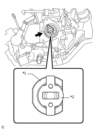
*1
Camshaft
*2
No. 1 Supply Pump Drive Coupling
Install the No. 1 supply pump drive coupling into the camshaft as shown in the illustration.
-
INSTALL SUPPLY PUMP ASSEMBLY
Note:When installing, clean the sealing surfaces of the fuel inlet pipe sub-assembly, supply pump assembly and common rail assembly.
-
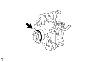
Apply a light coat of engine oil to a new O-ring.
Install the O-ring to the supply pump assembly.
-
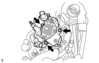
Temporarily install the supply pump assembly with the 3 bolts.
-
INSTALL FUEL INLET PIPE SUB-ASSEMBLY
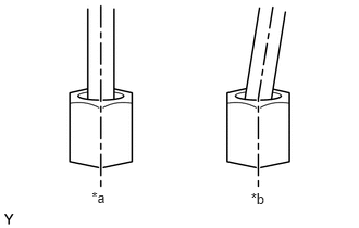
*a
Correct
*b
Incorrect
Note:When replacing the supply pump assembly, the fuel inlet pipe sub-assembly must also be replaced.
Replace the fuel inlet pipe sub-assembly with a new one when the fuel inlet pipe sub-assembly has been removed and reinstalled more than 5 times.
-
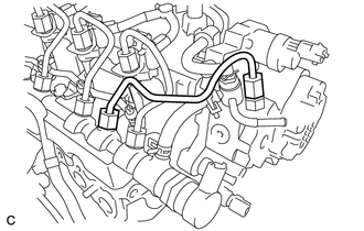
Temporarily install the fuel inlet pipe sub-assembly onto the supply pump assembly and common rail assembly.
Note:Install the fuel inlet pipe sub-assembly and union nut vertically, not at a tilt.
Tighten the supply pump assembly with the 3 bolts.
21 N*m
214 kgf*cm
15 ft.*lbf
Using a 17 mm union nut wrench, tighten the union nut on the common rail assembly side.
28 N*m
286 kgf*cm
21 ft.*lbf
Note:Use the torque value compensation formula to calculate the torque value for use when a torque wrench is combined with a tool such as a union nut wrench.
Using a 17 mm union nut wrench, tighten the union nut on the supply pump assembly side while holding the supply pump assembly with a 17 mm wrench.
28 N*m
286 kgf*cm
21 ft.*lbf
Note:Use the torque value compensation formula to calculate the torque value for use when a torque wrench is combined with a tool such as a union nut wrench.
-
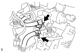
Connect the fuel hose and slide the clip to secure it.
Connect the nozzle leakage pipe assembly and install a new retainer spring onto the supply pump assembly.
-
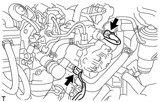
Connect the 2 connectors to the supply pump assembly.
-
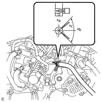
*a
Upper
*b
LH Side
*c
90°
Connect the No. 2 fuel hose and slide the clip to secure it.
Note:Engage the clip within the area shown in the illustration.
-
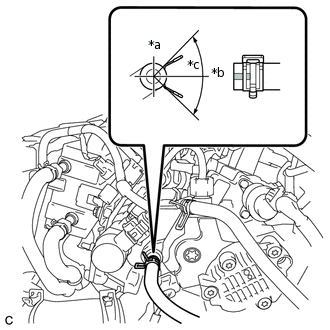
*a
Upper
*b
Front
*c
90°
Connect the No. 1 fuel hose and slide the clip to secure it.
Note:Engage the clip within the area shown in the illustration.
INSTALL NO. 1 EGR COOLER BRACKET
INSTALL AIR CLEANER CASE SUB-ASSEMBLY
INSTALL AIR CLEANER CAP SUB-ASSEMBLY
INSTALL EGR WITH COOLER PIPE SUB-ASSEMBLY
BLEED AIR FROM FUEL SYSTEM
INSPECT FOR FUEL LEAK