DIFFERENTIAL CASE REASSEMBLY
PROCEDURE
INSTALL FRONT DIFFERENTIAL SIDE GEAR
-
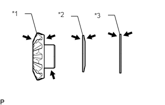
Apply gear oil to the front differential side gear, front differential side gear thrust washer and conical spring
Table 1. Text in Illustration *1
Front Differential Side Gear
*2
Conical Spring
*3
front differential side gear thrust washer

Gear Oil
-
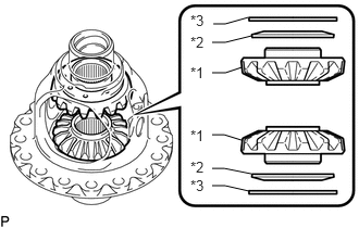
Install the 2 front differential side gears, 2 front differential side gear thrust washers and 2 conical springs to the front No. 1 differential case sub-assembly.
Table 2. Text in Illustration *1
Front Differential Side Gear
*2
Conical Spring
*3
front differential side gear thrust washer
Note:Do not drop the front differential side gear, front differential side gear thrust washer and conical spring.
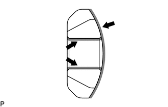
Make sure that the conical spring is installed in the correct direction.
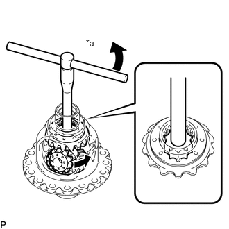
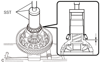
Set SST as shown in the illustration and tighten it.
09528-52010
09953-05010
09528-05010
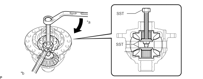
Table 3. Text in Illustration *a
Turn
*b
Hold
Tip:Tighten SST until the front differential pinion can enter the front No. 1 differential case sub-assembly.
When installing the front differential pinion, do not overtighten SST, as it is necessary to rotate the front differential side gear.
-
Apply gear oil to the front differential pinion thrust washer.
Table 4. Text in Illustration Gear Oil
-
Apply gear oil to the front differential pinion.
Table 5. Text in Illustration Gear Oil
-
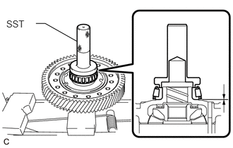
Using SST as shown in the illustration, rotate the front differential side gear and install the 2 front differential pinions and 2 front differential pinion thrust washers.
09528-52010
09528-05030
Table 6. Text in Illustration *a
Turn
CAUTION:Be careful not to catch your fingers between the front differential pinion and front No. 1 differential case sub-assembly.
Note:Do not drop the front differential pinion and front differential pinion thrust washer.
-
INSPECT FRONT DIFFERENTIAL PINIONBACKLASH
INSTALL FRONT NO. 1 DIFFERENTIAL PINIONSHAFT
-
Apply gear oil to the front No. 1 differential pinion shaft.
Table 7. Text in Illustration Gear Oil
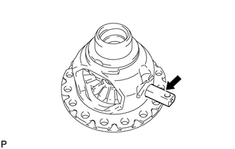
Install the front No. 1 differential pinion shaft to the front No. 1 differential case sub-assembly so that the hole for the front differential pinion shaft straight pin is aligned with the hole in the front No. 1 differential case sub-assembly.
-
INSPECT FRONT NO. 1 DIFFERENTIAL CASE SUB-ASSEMBLY
INSTALL FRONT DIFFERENTIAL PINION SHAFT STRAIGHT PIN
-
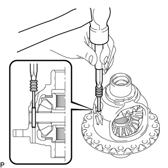
Using a 5 mm pin punch and hammer, tap in the front differential pinion shaft straight pin to the front No. 1 differential case sub-assembly.
-
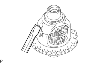
Using a chisel and hammer, stake the front No. 1 differential case sub-assembly.
-
INSTALL FRONT DIFFERENTIAL RING GEAR
Clean the contact surfaces of the front No. 1 differential case sub-assembly and front differential ring gear.
Using a heater, heat the front differential ring gear to 90 to 110°C (194 to 230°F) in boiling water.
-
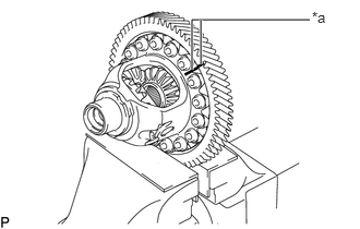
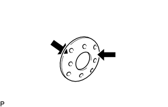
After the moisture on the front differential ring gear has completely evaporated, quickly align the matchmarks on the front differential ring gear and the front No. 1 differential case sub-assembly and install the front differential ring gear to the front No. 1 differential case sub-assembly.
Table 8. Text in Illustration *a
Matchmark
Install the 16 bolts.
106 N*m
1081 kgf*cm
78 ft.*lbf
INSTALL FRONT DIFFERENTIAL CASE FRONT TAPERED ROLLER BEARING
-
Using SST and a press, press in a new front differential case front tapered roller bearing.
09523-36010
09950-60010
09951-00460
09951-00560
09952-06010
09950-70010
09951-07150
-
INSTALL FRONT DIFFERENTIAL CASE REAR TAPERED ROLLER BEARING
-
Using SST and a press, press in a new front differential case rear tapered roller bearing.
09554-22010
-