STOP LIGHT SWITCH INSTALLATION
PROCEDURE
-
INSTALL STOP LIGHT SWITCH ASSEMBLY
-
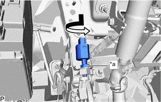
*a Stop Light Switch Lock Nut Temporarily install the stop light switch assembly with the stop light switch lock nut as shown in the illustration.
-
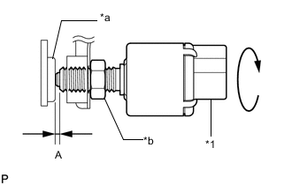
*1 Stop Light Switch Assembly *a Cushion *b Stop Light Switch Lock Nut Turn the stop light switch assembly so that the clearance between the end of the threads and cushion is within A.
Part Measurement A 0.87 to 2.4 mm (0.0343 to 0.0945 in.) -
Tighten the stop light switch lock nut.
- Torque:
- 16.7 N*m { 170 kgf*cm, 12 ft.*lbf }
-
Connect the connector.
-
If the protrusion is not as specified, recheck switch installation and perform brake pedal adjustment if necessary.
for LHD Click here Click here for RHD Click here Click here Note
Do not depress or support the brake pedal.
-
-
INSTALL NO. 1 INSTRUMENT PANEL UNDER COVER SUB-ASSEMBLY