ECM REMOVAL
PROCEDURE
-
PRECAUTION
Note
-
After turning the power switch off, waiting time may be required before disconnecting the cable from the negative (-) auxiliary battery terminal. Therefore, make sure to read the disconnecting the cable from the negative (-) auxiliary battery terminal notice before proceeding with work Click here.
-
Perform the Vehicle Identification Number (VIN) registration when replacing the ECM Click here.
HV battery learning values are stored in the hybrid vehicle control ECU and ECM and are used to detect malfunctions and illuminate the hybrid battery indicator light in the combination meter assembly. When either of these ECUs is replaced, the new ECU receives the HV battery learning values from the other ECU and stores them.
Note
-
Do not replace the hybrid vehicle control ECU and ECM at the same time as the HV battery learning values will be lost. However, if it is necessary to replace both ECUs at the same time, replace them by following the procedure below.
-
Do not replace the hybrid vehicle control ECU or ECM with a used one from another vehicle.
-
Procedure when replacing both hybrid vehicle control ECU and ECM:
-
Disconnect the cable from the negative (-) auxiliary battery terminal.
-
Replace either ECU.
-
Connect the cable to the negative (-) auxiliary battery terminal.
-
Turn the power switch on (READY) and wait for 5 minutes or more.
-
Turn the power switch off and disconnect the cable from the negative (-) auxiliary battery terminal.
-
Replace the other ECU.
-
Connect the cable to the negative (-) auxiliary battery terminal.
-
Check that the power switch can be turned on (READY).
Tech Tips
If the hybrid vehicle control ECU and ECM are replaced at the same time without following the above procedure, replace either of the ECUs with its original one and then replace it again by following the above procedure. If the correct procedure is not followed, perform the procedure again from the beginning.
-
-
-
REMOVE DECK BOARD ASSEMBLY
-
REMOVE NO. 1 DECK BOARD
-
REMOVE NO. 2 DECK BOARD
-
REMOVE REAR DECK FLOOR BOX
-
REMOVE DECK FLOOR BOX RH
-
DISCONNECT CABLE FROM NEGATIVE AUXILIARY BATTERY TERMINAL
Note
When disconnecting the cable, some systems need to be initialized after the cable is reconnected Click here.
-
REMOVE INVERTER WITH CONVERTER ASSEMBLY
-
SEPARATE INVERTER RESERVE TANK ASSEMBLY
-
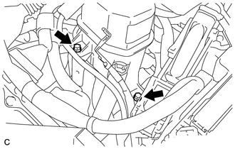
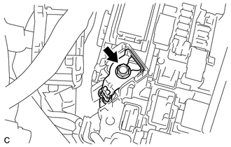
Remove the 2 bolts and separate the inverter reserve tank assembly.
-
-
REMOVE ECM
-
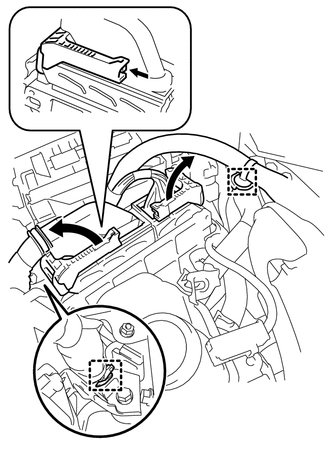
Remove the No. 1 relay block cover.
-
Disconnect the 3 wire connectors.
-
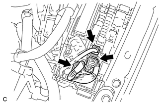
Disengage the 2 claws, push up the engine room wire harness and separate it from the engine room relay block.
-
Disengage the 2 claws and push up the side cover to remove it.
-
Loosen the bolt and separate the No. 2 engine room wire.
-
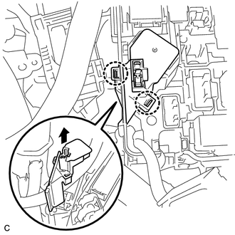
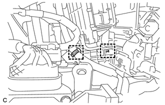
Disconnect the 2 ECM connectors.
-
Disconnect the 2 wire harness clamps.
-
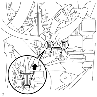
Push the locks on the 2 levers, then raise the levers, and disconnect the 2 ECM connectors.
Note
After disconnecting the connectors, make sure that dirt, water or other foreign matter does not contact the connecting parts of the connectors.
-
-
Separate the 2 wire harness clamps.
-
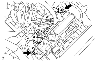
Remove the 2 bolts and ECM.
-