AIR CONDITIONING SYSTEM
-
SYSTEM CONTROL
-
The air conditioning system uses the following controls:
Control Outline Neural Network Control*1 This control is capable of effecting complex control by artificially simulating the information processing method of the nervous system of living organisms in order to establish a complex input/output relationship that is similar to that of a human brain. Pollen Removal Mode Control*1, *2 Activated by the pollen removal mode switch operation. Switches the air outlet to the FACE mode. Sends air which has passed through the clean air filter to the area around the upper part of the bodies of the driver and front passenger. This air is filtered by the clean air filter in order to remove pollen. Outlet Air Temperature Control*1 Based on the temperature set at the temperature control switch, the neural network control calculates the outlet air temperature based on the input signals from various sensors. The temperature settings for the driver and front passenger are controlled independently in order to provide a separate vehicle interior temperature for the right and left sides of the vehicle. As a result, air conditioning control that accommodates occupant preferences has been achieved. Blower Control*1 Controls the blower motor in accordance with the airflow volume that has been calculated by the neural network control based on the input signals from various sensors. Air Outlet Control*1 Automatically switches the air outlets in accordance with the outlet mode that has been calculated by the neural network control based on the input signals from various sensors. Cooler Compressor Control Controls the blower motor in accordance with the airflow volume that has been calculated by the neural network control based on the input signals from various sensors. Blower Customization*3 Controls the blower motor speed in accordance with the blower mode setting. Rear Window Defogger Control Switches the rear window defogger on for 15 minutes when the rear window defogger switch is pressed. Switches the rear window defogger off if the switch is pressed while it is operating.
-
*1: Models with automatic air conditioning system
-
*2: Models without blower customization control
-
*3: Models with blower customization control
-
-
Neural Network Control
-
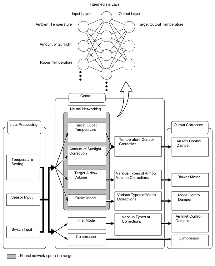
In the previous automatic air conditioning system, the air conditioning amplifier assembly determined the required outlet air temperature and blower air volume in accordance with a calculation formula that had been obtained based on information received from the sensors. However, because the sensors of a person are rather complex, a given temperature is sensed differently, depending on the environment in which the person is situated. For example, a given amount of solar radiation can feel comfortably warm in a cold climate, but extremely uncomfortable in a hot climate. Therefore, as a technique for effecting a high level of control, a neural network is used in the automatic air conditioning system. With this technique, the data that has been collected under varying environmental conditions is stored in the air conditioning amplifier assembly, which effects control to provide enhanced air conditioning comfort.
-
The neural network control consists of neurons in an input layer an intermediate layer, and an output layer. The input layer neurons process the input data of the ambient temperature, the amount of sunlight and the room temperature based on the outputs of the switches and sensors, and output them to the intermediate layer neurons. Based on this data, the intermediate layer neurons adjust the strength of the links among the neurons. The sum of this data is then calculated by the output layer neurons in the form of the required outlet temperature, solar correction, target airflow volume and outlet mode control volume. Accordingly, the air conditioning amplifier assembly controls the servo motors and blower with fan motor sub-assembly in accordance with the control volumes that have been calculated by the neural network control.
-
-
Quick Heater Control (Models with Quick Heater Assembly)
-
The on/off function of the quick heater assembly is controlled by the air conditioning amplifier assembly in accordance with the engine coolant temperature, engine speed, air mix setting and electrical load (alternator power ratio).
-
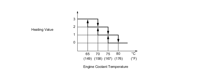
For example, the heating value of the operating quick heater assembly varies depending on the engine coolant temperature, as in the graph below:
Figure 1. Heating Value of Operating Quick Heater Assembly
-
-
Combustion Type Power Heater (Models with Combustion Type Power Heater)
-
Igniting
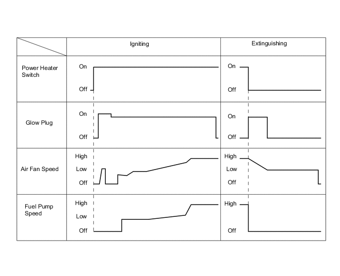
When the engine is operating, turning the heater switch assembly on causes the air fan to operate for several seconds for verification purposes. Then, the glow plug starts to preheat the combustion chamber. After that, the fuel pump and air fan turn on in order to start low combustion. The fuel pump speed is then increased in steps, and this is accompanied by a gradual increase in the speed of the air fan, thus leading to high combustion.
-
Extinguishing
When the ignition switch is turned off or the heater switch assembly is turned off, the fuel pump stops, causing the combustion to stop. For the purpose of after-purge, current is applied again to the glow plug, and the air fan is activated for several seconds. Then, the entire system comes to a stop.
Figure 2. Timing Chart
-
Operating
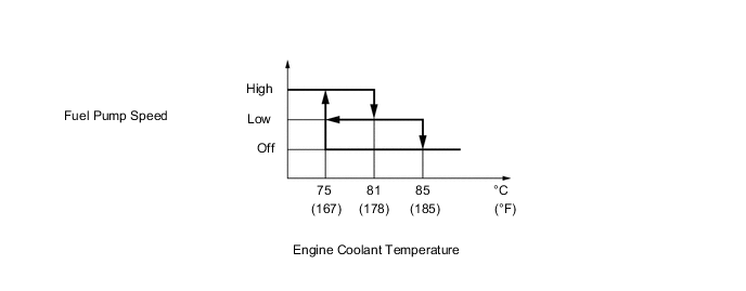
While the system is in operation, it controls the fuel pump speed and switches between high combustion and low combustion, constantly keeping the engine coolant temperature between 75 °C (167 °F) and 85 °C (185 °F). If the engine coolant temperature exceeds 85 °C (185 °F), the fuel pump stops automatically to stop the combustion. Thereafter, when the engine coolant temperature reaches 75 °C (167 °F) or below, ignition occurs again. The operation of the glow plug, the air fan, and the fuel pump during extinguishing and re-igniting is the same as when these are operated by a switch as mentioned previously.
Figure 3. Coolant Temperature Control
-
Protective Control
For self-protection, this system stops if an abnormal condition is detected. Descriptions of the control are indicated below.
Function Control Dry Run Prevention If the temperature detected by the engine coolant temperature sensor or the overheating prevention sensor exceeds 125 °C (257 °F), the air conditioning amplifier assembly determines that the heater is operating without water and automatically stops the system. Overheating Prevention If the difference in temperature detected by the engine coolant temperature sensor and the overheating prevention sensor exceeds 25 °C (77 °F), the air conditioning amplifier assembly determines that the flow volume of the water is insufficient and automatically stops the system. Non-ignition or Misfiring Detection If the temperature of the exhaust gas detected by the flame sensor is low, the air conditioning amplifier assembly determines that a non-ignition or a misfiring condition exists and automatically stops the system. Open or Short Circuit Detection If an open or short circuit exists in the sensors or actuators, the air conditioning amplifier assembly automatically stops the system. Air Fan Seizure Detection If the air fan seizes, the air conditioning amplifier assembly automatically stops the system.
-
-
Pollen Removal Mode Control (Models with Pollen Removal Mode)
-
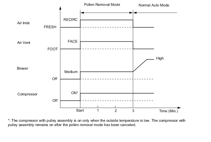
When the pollen removal mode switch is pressed, the pollen removal mode control is activated. Then, the air outlet is switched to the FACE mode and recirculated pollen-free air flows in the area around the upper part of the bodies of the driver and front passenger.
-
When the pollen removal mode switch signal is input to the air conditioning amplifier assembly, the air conditioning amplifier assembly controls the compressor with pulley assembly, No. 1 damper servo sub-assembly, No. 3 air conditioning radiator damper servo sub-assembly and blower with fan motor sub-assembly as shown in the timing chart below.
-
This control usually operates for approximately 3 minutes. However, when the ambient temperature is low [5 °C (41 °F) maximum], it will operate for approximately 1 minute.
-
After this control stops operating, the air conditioning amplifier assembly automatically returns to the mode it was in just before the pollen removal mode switch was pressed.
-
-
-
Blower Customization Control (Models with Blower Customization Control)
-
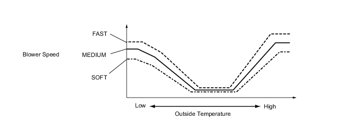
By pressing the FAST/SOFT switch of the air conditioning control assembly, the blower speed calculated by the neural network is changed in 3 stages and controlled.
-
When in DEF mode, blower customization control is turned off.
-
-