PARKING BRAKE ASSEMBLY REASSEMBLY

PROCEDURE
-
INSTALL PARKING BRAKE SHOE HOLD DOWN SPRING PIN (for Rear Side)
-
Clean the installation surface of the parking plate sub-assembly.
-
Install the parking brake shoe hold down spring pin.
-
Temporarily install the parking plate sub-assembly to the rear axle hub and bearing assembly with the nut.
Note
Make sure that the No. 3 parking brake cable assembly is not twisted during reassembly.
Tech Tips
The parking plate sub-assembly will be fully installed after installing the rear axle hub and bearing assembly.
-
Install the rear axle hub and bearing assembly Click here.
-
Fully tighten the installation nut of the parking plate sub-assembly.
- Torque:
- 140 N*m { 1428 kgf*cm, 103 ft.*lbf }
-
-
INSTALL PARKING BRAKE SHOE HOLD DOWN SPRING PIN (for Front Side)
-
Install the parking brake shoe hold down spring pin.
-
-
APPLY HIGH TEMPERATURE GREASE
-
Apply high temperature grease to the areas of the parking brake plate which make contact with the shoe as shown in the illustration.
Text in Illustration 
High Temperature Grease
-
-
INSTALL PARKING BRAKE SHOE LEVER
-
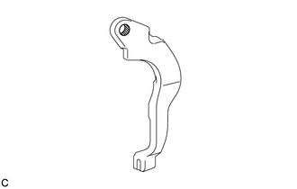
Apply high temperature grease to the areas of the parking brake shoe lever which make contact with the No. 2 parking brake shoe assembly.
Text in Illustration High Temperature Grease -
Temporarily install the parking brake shoe lever to the No. 2 parking brake shoe assembly with a new parking brake shoe type C washer.
-
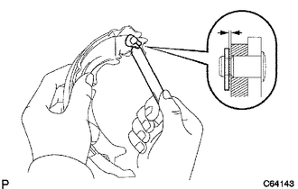
Using a feeler gauge, measure the clearance between the No. 2 parking brake shoe assembly and parking brake shoe lever.
Standard clearance Less than 0.35 mm (0.0137 in.) If the clearance is not as specified, replace the parking brake shoe shim with one of the correct size.
Part No. Shim Thickness 90564-09184 0.3 mm (0.0118 in.) 90564-09185 0.6 mm (0.0236 in.) 90564-09186 0.9 mm (0.0354 in.) -
Select a parking brake shoe shim and install it and the parking brake shoe type C washer.
-
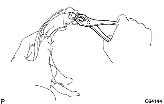
Using a pair of pliers, squeeze together the ends of the parking brake shoe type C washer.
-
Check that the parking brake shoe lever moves smoothly.
-
-
CONNECT PARKING BRAKE SHOE LEVER
-
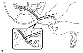
Using needle-nose pliers, connect the No. 3 parking brake cable assembly to the parking brake shoe lever.
-
-
INSTALL PARKING BRAKE SHOE RETURN TENSION SPRING (for Lower Side)
-
Install the parking brake shoe return tension spring to the No. 2 parking brake shoe assembly.
-
-
INSTALL NO. 1 PARKING BRAKE SHOE ASSEMBLY
-
Install the No. 1 parking brake shoe assembly to the parking brake shoe return tension spring.
-
-
INSTALL PARKING BRAKE SHOE ADJUSTING SCREW SET
-
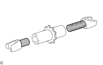
Apply high temperature grease to the parking brake shoe adjusting screw set as shown in the illustration.
Text in Illustration High Temperature Grease -
Install the parking brake shoe adjusting screw set to the No. 1 parking brake shoe assembly and No. 2 parking brake shoe assembly.
-
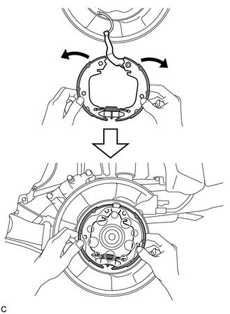
Expand the No. 1 and No. 2 parking brake shoe assemblies outward by hand and fit them to the parking brake plate.
Note
Make sure that the parking brake shoe lever does not separate from the No. 2 parking brake shoe assembly.
-
-
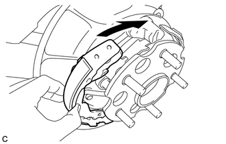
INSTALL BRAKE SHOE HOLD DOWN SPRING (for Rear Side)
-
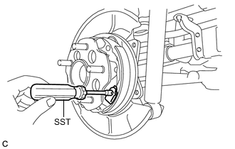
Using SST, install the brake shoe hold down spring as shown in the illustration.
- SST
- 09718-00011
-
-
INSTALL PARKING BRAKE SHOE STRUT
-
Install the parking brake shoe strut.
-
Install the No. 1 parking brake shoe assembly.
-
-
INSTALL BRAKE SHOE HOLD DOWN SPRING (for Front Side)
-
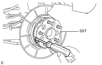
Using SST, install the brake shoe hold down spring as shown in the illustration.
- SST
- 09718-00011
-
-
INSTALL PARKING BRAKE SHOE RETURN TENSION SPRING (for Rear Side)
-
Install the parking brake shoe return tension spring.
-
-
INSTALL PARKING BRAKE SHOE RETURN TENSION SPRING (for Front Side)
-
Install the parking brake shoe return tension spring.
-
-
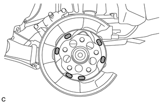
CHECK PARKING BRAKE INSTALLATION
-
Check that each part is installed properly.
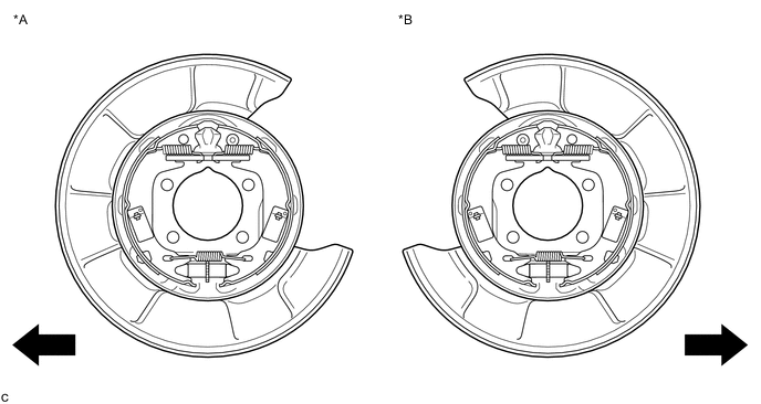
Text in Illustration *A LH Side *B RH Side 
Front of the Vehicle - - Note
There should be no oil or grease on the friction surfaces of the shoe linings or discs.
-
-
INSTALL REAR DISC
-
INSTALL PARKING BRAKE SHOE ADJUSTING HOLE PLUG
-
INSTALL REAR DISC BRAKE CALIPER ASSEMBLY
-
ADJUST PARKING BRAKE SHOE CLEARANCE AND PARKING BRAKE PEDAL TRAVEL
-
for LHD: Click here
-
for RHD: Click here
-
-
INSTALL REAR WHEEL
- Torque:
- 103 N*m { 1050 kgf*cm, 76 ft.*lbf }
-
CONNECT CABLE TO NEGATIVE AUXILIARY BATTERY TERMINAL
-
Connect the cable to the negative (-) auxiliary battery terminal Click here.
-
Connect the reservoir level switch connector.
-
Clear the DTCs Click here.
-
-
BED IN PARKING BRAKE SHOES TO DISCS
-
Drive the vehicle at about 50 km/h (31 mph) on a safe, level and dry road.
-
Depress the parking brake pedal with 150 N (15 kgf, 33.7 lbf) of force.
-
Drive the vehicle for about 400 m (0.25 mile) in this condition.
-
Repeat this procedure 3 times.
Note
Set a 5-minute interval between each procedure to prevent the brake assembly from overheating.
-