FRONT DRIVE SHAFT ASSEMBLY REASSEMBLY

PROCEDURE
-
INSTALL FRONT DRIVE SHAFT BEARING (for RH Side)
-
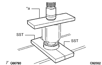
*a Steel Plate Using SST, a steel plate and a press, install a new front drive shaft bearing.
- SST
- 09527-10011
Note
The bearing should be completely installed.
-
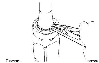
Using a snap ring expander, install a new drive shaft hole snap ring.
Note
Install the drive shaft hole snap ring securely.
-
-
INSTALL FRONT DRIVE SHAFT DUST COVER LH
-
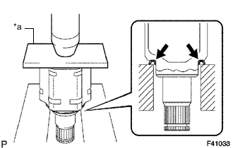
*a Steel Plate Using a steel plate and a press, install a new front drive shaft dust cover LH.
Note
-
Make sure to fully install the front drive shaft dust cover LH.
-
Be careful not to damage the front drive shaft dust cover LH.
-
-
-
INSTALL FRONT DRIVE SHAFT DUST COVER RH (for 2WD RH Side)
-
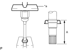
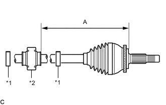
*a Steel Plate Using a steel plate and a press, install a new front drive shaft dust cover RH until the dimension (A) from the tip of the front drive inboard joint assembly to the front drive shaft dust cover RH meets the specification.
Dimension (A) 115.5 to 116.5 mm (4.55 to 4.58 in.) Note
Be careful not to damage the front drive shaft dust cover RH.
-
-
INSTALL FRONT AXLE OUTBOARD JOINT BOOT (for LH Side)
-
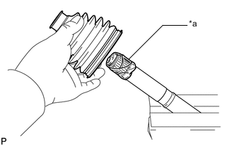
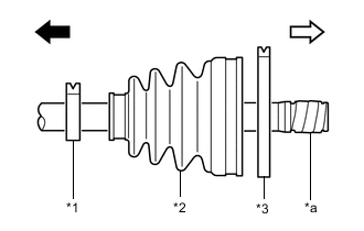
*a Protective Tape Wrap the splines of the front drive outboard joint shaft assembly with protective tape to prevent the boot from being damaged.
-
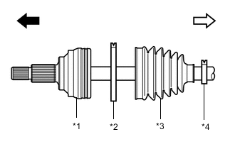
*1 Front Drive Outboard Joint Shaft Assembly *2 Front No. 2 Axle Outboard Joint Boot Clamp *3 Front Axle Outboard Joint Boot *4 Front Axle Outboard Joint Boot Clamp 
Outboard joint side 
Inboard joint side Install new parts to the front drive outboard joint shaft assembly in the following order:
-
Front No. 2 axle outboard joint boot clamp
-
Front axle outboard joint boot
-
Front axle outboard joint boot clamp
-
-
Pack the joint portion of the front drive outboard joint shaft assembly and front axle outboard joint boot with grease.
Standard Grease Capacity 81 to 91 g (2.86 to 3.20 oz) -
Install the front axle outboard joint boot to the front drive outboard joint shaft assembly groove.
Note
-
Do not allow grease to adhere to the boot clamp track of the outboard joint boot.
-
Keep the inside of the outboard joint boot free of foreign matter.
-
-
-
INSTALL FRONT AXLE OUTBOARD JOINT BOOT CLAMP (for LH Side)
-
Secure the drive shaft in a vise between aluminum plates.
Note
Do not overtighten the vise.
-
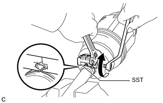
Install the front axle outboard joint boot clamp to the front axle outboard joint boot.
-
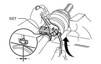
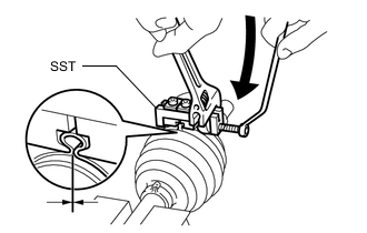
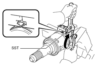
Place SST onto the front axle outboard joint boot clamp, press it against the boot and slightly tighten SST.
- SST
- 09521-24010
-
Tighten SST so that the front axle outboard joint boot clamp is pinched.
Note
Do not overtighten SST.
-
Remove SST.
-
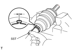
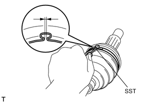
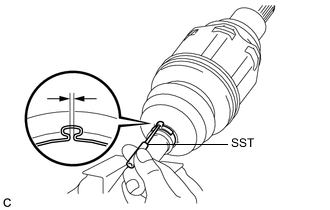
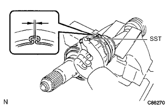
Using SST, measure the clearance of the front axle outboard joint boot clamp.
- SST
- 09240-00020
Clearance 0.5 to 1.5 mm (0.0197 to 0.0590 in.) If the clearance is not as specified, retighten SST.
-
-
INSTALL FRONT NO. 2 AXLE OUTBOARD JOINT BOOT CLAMP (for LH Side)
-
Secure the drive shaft in a vise between aluminum plates.
Note
Do not overtighten the vise.
-
Install the front No. 2 axle outboard joint boot clamp to the front axle outboard joint boot.
-
Place SST onto the front No. 2 axle outboard joint boot clamp, press it against the boot and slightly tighten SST.
- SST
- 09521-24010
-
Tighten SST so that the front No. 2 axle outboard joint boot clamp is pinched.
Note
Do not overtighten SST.
-
Remove SST.
-
Using SST, measure the clearance of the front No. 2 axle outboard joint boot clamp.
- SST
- 09240-00020
Clearance 0.5 to 1.5 mm (0.0197 to 0.0590 in.) If the clearance is not as specified, retighten SST.
-
-
INSTALL FRONT AXLE OUTBOARD JOINT BOOT (for 2WD RH Side)
Tech Tips
Perform the same procedure as for the LH side.
-
INSTALL FRONT AXLE OUTBOARD JOINT BOOT CLAMP (for 2WD RH Side)
Tech Tips
Perform the same procedure as for the LH side.
-
INSTALL FRONT NO. 2 AXLE OUTBOARD JOINT BOOT CLAMP (for 2WD RH Side)
Tech Tips
Perform the same procedure as for the LH side.
-
INSTALL FRONT DRIVE SHAFT DAMPER (w/ Drive Shaft Damper)
-
*1 Front Drive Shaft Damper Clamp *2 Front Drive Shaft Damper Temporarily install the front drive shaft damper and 2 new front drive shaft damper clamps to the front drive outboard joint shaft assembly as shown in the illustration.
-
Set the dimension (A) as specified below.
Dimension (A) for LH Side 235.0 to 239.0 mm (9.26 to 9.40 in.) for RH Side 240.0 to 244.0 mm (9.45 to 9.60 in.) -
Install the 2 front drive shaft damper clamps to the front drive shaft damper.
Note
Make sure to install the clamps in the correct position.
-
-
INSTALL FRONT DRIVE SHAFT DAMPER CLAMP (w/ Drive Shaft Damper)
-
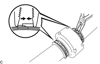
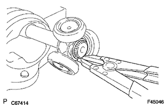
Using needle nose pliers, install the 2 front drive shaft damper clamps.
-
-
INSTALL FRONT DRIVE INBOARD JOINT ASSEMBLY
-
*1 Front Axle Inboard Joint Boot Clamp *2 Front Axle Inboard Joint Boot *3 Front No. 2 Axle Inboard Joint Boot Clamp *a Protective Tape Outboard joint side Inboard joint side Install new parts to the front drive outboard joint shaft assembly in the following order:
-
Front axle inboard joint boot clamp
-
Front axle inboard joint boot
-
Front No. 2 axle inboard joint boot clamp
-
-
Secure the drive shaft in a vise between aluminum plates.
Note
Do not overtighten the vise.
-
Remove the protective tape.
-
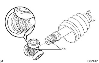
*a Matchmark Align the matchmarks and install the tripod joint to the front drive outboard joint shaft assembly.
Note
Face the serrated side of the tripod joint outward and install it to the outboard joint end.
-
Using a brass bar and a hammer, install the tripod joint to the front drive outboard joint shaft assembly.
Note
-
Do not tap the rollers.
-
Keep the tripod joint free of foreign matter.
-
Make sure to install the tripod joint in the correct direction.
-
-
Using a snap ring expander, install a new shaft snap ring to the front drive outboard joint shaft assembly.
-
Pack the front drive inboard joint assembly and front axle inboard boot with grease.
Standard Grease Capacity 190 to 210 g (6.71 to 7.40 oz) -
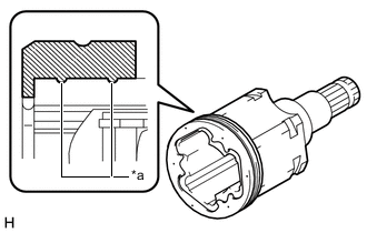
*a Lip Install a new front axle inboard joint grommet to the front drive inboard joint assembly.
Note
-
Securely fit the protrusion on the front axle inboard joint grommet into the front drive inboard joint assembly.
-
Make sure that the lip of the front axle inboard joint grommet is not damaged.
-
-
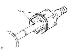
*a Matchmark Align the matchmarks and install the front drive inboard joint assembly to the front drive outboard joint shaft assembly.
-
-
INSTALL FRONT AXLE INBOARD JOINT BOOT
-
Install the front axle inboard joint boot to the front drive inboard joint assembly.
-
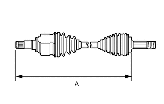
Check whether the dimension (A) of each drive shaft is within specification.
Dimension (A) for LH Side 600.85 mm (1.97 ft.) for RH Side 2WD 925.55 mm (3.04 ft.) AWD 926.55 mm (3.04 ft.)
-
-
INSTALL FRONT AXLE INBOARD JOINT BOOT CLAMP
-
Secure the drive shaft in a vise between aluminum plates.
Note
Do not overtighten the vise.
-
Install the front axle inboard joint boot clamp to the front axle inboard joint boot.
-
Place SST onto the front axle inboard joint boot clamp, press it against the boot and slightly tighten SST.
- SST
- 09521-24010
-
Tighten SST so that the front axle inboard joint boot clamp is pinched.
Note
Do not overtighten SST.
-
Remove SST.
-
Using SST, measure the clearance of the front axle inboard joint boot clamp.
- SST
- 09240-00020
Clearance 0.5 to 1.5 mm (0.0197 to 0.0590 in.) If the clearance is not as specified, retighten SST.
-
-
INSTALL FRONT NO. 2 AXLE INBOARD JOINT BOOT CLAMP
-
Secure the drive shaft in a vise between aluminum plates.
Note
Do not overtighten the vise.
-
Install the front No. 2 axle inboard joint boot clamp to the front axle inboard joint boot.
-
Place SST onto the front No. 2 axle inboard joint boot clamp, press it against the boot and slightly tighten SST.
- SST
- 09521-24010
-
Tighten SST so that the front No. 2 axle inboard joint boot clamp is pinched.
Note
Do not overtighten SST.
-
Remove SST.
-
Using SST, measure the clearance of the front No. 2 axle inboard joint boot clamp.
- SST
- 09240-00020
Clearance 0.5 to 1.5 mm (0.0197 to 0.0590 in.) If the clearance is not as specified, retighten SST.
-
-
INSPECT FRONT DRIVE SHAFT ASSEMBLY