SPEED LIMITER SYSTEM TERMINALS OF ECM
CHECK ECM (for 1ZR-FAE, 2ZR-FAE)
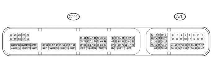
Disconnect the A76 and C111 ECM connectors.
Measure the voltage and resistance according to the value(s) in the table below.
Terminal No. (Symbol)
Wiring Color
Terminal Description
Condition
Specified Condition
A76-1 (BATT) - Body ground
P - Body ground
Power source circuit
Always
11 to 14 V
A76-6 (IGSW) - Body ground
B - Body ground
IG power source circuit
Ignition switch ON
11 to 14 V
Ignition switch off
Below 1 V
A76-20 (ASLM) - Body ground
GR - Body ground
Speed limiter main switch signal
Speed limiter main switch on
Below 1 Ω
Speed limiter main switch off
10 kΩ or higher
C111-59 (E1) - Body ground
BR - Body ground
Ground
Always
Below 1 Ω
If the result is not as specified, there may be a malfunction on the wire harness side.
CHECK ECM (for 1WW)
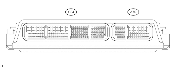
Disconnect the A76 ECM connectors.
Measure the voltage and resistance according to the value(s) in the table below.
Terminal No. (Symbol)
Wiring Color
Terminal Description
Condition
Specified Condition
A76-15 (BATT) - Body ground
B - Body ground
Power source circuit
Always
11 to 14 V
A76-37 (B) - Body ground
B - Body ground
IG power source circuit
Ignition switch ON
11 to 14 V
Ignition switch off
Below 1 V
A76-49 (ASLM) - Body ground
GR - Body ground
Speed limiter main switch signal
Speed limiter main switch on
Below 1 Ω
Speed limiter main switch off
10 kΩ or higher
A76-4 (E1) - Body ground
W-B - Body ground
Ground
Always
Below 1 Ω
If the result is not as specified, there may be a malfunction on the wire harness side.