ROOF HEADLINING (for Double Cab) INSTALLATION
Tech Tips
-
Use the same procedure for RHD and LHD vehicles.
-
The procedure listed below is for LHD vehicles.
-
INSTALL REAR NO. 3 SIDE RAIL SPACER LH
-
Attach the 3 claws to install the rear No. 3 side rail spacer.
-
-
INSTALL REAR NO. 3 SIDE RAIL SPACER RH
Tech Tips
Use the same procedure described for the LH side.
-
INSTALL REAR NO. 2 SIDE RAIL SPACER LH
Tech Tips
Use the same procedure for both rear No. 2 side rail spacers.
-
Attach the 2 claws to install the rear No. 2 side rail spacer
-
-
INSTALL REAR NO. 2 SIDE RAIL SPACER RH
Tech Tips
Use the same procedure described for the LH side.
-
INSTALL SIDE RAIL SPACER (for LHD)
-
Attach the 2 claws to install the side rail spacer.
-
-
INSTALL SIDE RAIL SPACER (for RHD)
Tech Tips
Use the same procedure described for the LHD.
-
INSTALL FRONT SIDE RAIL SPACER LH
-
Attach the 2 claws to install the front side rail spacer.
-
-
INSTALL FRONT SIDE RAIL SPACER RH
Tech Tips
Use the same procedure described for the LH side.
-
INSTALL ROOF HEADLINING ASSEMBLY
-
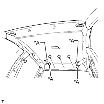
for LHD:
-
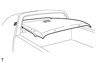
Place the roof headlining into the vehicle as shown in the illustration.
Note
Be careful not to damage the roof headlining when placing it.
-
Text in Illustration *A w/o Assist Grip Install the roof headlining with the clips.
-
Connect the connectors and attach the 4 clamps.
-
-
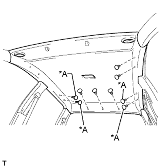
for RHD:
-
Place the roof headlining into the vehicle as shown in the illustration.
Note
Be careful not to damage the roof headlining when placing it.
-
Install the roof headlining with the clips.
-
Connect the connectors and attach the 5 clamps.
Text in Illustration *A w/o Assist Grip
-
-
Attach the 5 clamps to the front pillar.
-
-
INSTALL BACK WINDOW GLASS
-
INSTALL DEFROSTER NOZZLE ASSEMBLY (w/ Defroster)
-
Attach the 4 clips to install the defroster nozzle assembly.
-
-
INSTALL NO. 3 HEATER TO REGISTER DUCT
-
Attach the 4 claws to install the No. 3 heater to register duct.
-
Install the clip.
-
-
INSTALL NO. 1 HEATER TO REGISTER DUCT
-
Attach the 3 claws to install the No. 1 heater to register duct.
-
Install the clip.
-
-
INSTALL NO. 2 HEATER TO REGISTER DUCT
-
Install the No. 2 heater to register duct with the 3 clips.
-
-
INSTALL LOWER INSTRUMENT PANEL FINISH PANEL SUB-ASSEMBLY
-
Attach the 3 guides, 2 claws and 3 clips to install the lower instrument panel finish panel.
-
-
INSTALL UPPER INSTRUMENT PANEL SUB-ASSEMBLY
-
INSTALL ASSIST GRIP (w/ Assist Grip)
Tech Tips
Use the same procedure for all assist grips.
-
Install the assist grip with the 2 screws.
-
Install the screw.
-
-
INSTALL VISOR HOLDER LH
-
Attach the 2 claws to install the visor holder.
-
Install the screw.
-
-
INSTALL VISOR HOLDER RH
Tech Tips
Use the same procedure described for the LH side.
-
INSTALL VISOR ASSEMBLY LH
-
Install the visor with the 2 screws.
-
Attach the guide.
-
-
INSTALL VISOR ASSEMBLY RH
Tech Tips
Use the same procedure described for the LH side.
-
INSTALL NO. 1 ROOM LIGHT ASSEMBLY
-
Connect the light connector.
-
Install the room light with the 2 screws.
-
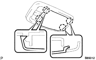
Attach the lens with the 4 claws.
-
-
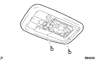
INSTALL MAP LIGHT ASSEMBLY
-
Connect the connector.
-
Attach the 2 guides and claw.
-
Install the 2 screws to install the map light assembly.
-
-
INSTALL QUARTER INSIDE TRIM BOARD LH
-
Attach the 4 clips to install the quarter inside trim board.
-
Connect the rear seat belt shoulder anchor with the bolt.
- Torque:
- 42 N*m { 428 kgf*cm, 31 ft.*lbf }
-
Attach the 2 claws to close the rear seat belt shoulder anchor cover.
-
-
INSTALL QUARTER INSIDE TRIM BOARD RH
Tech Tips
Use the same procedure described for the LH side.
-
INSTALL LOWER QUARTER TRIM PANEL LH
-
Attach the 3 clips and claw to install the lower quarter trim panel.
-
-
INSTALL LOWER QUARTER TRIM PANEL RH
Tech Tips
Use the same procedure described for the LH side.
-
INSTALL UPPER BACK PANEL GARNISH
-
Attach the 5 clips and 4 claws to install the upper back panel garnish.
-
-
INSTALL CENTER PILLAR GARNISH LH
-
Attach the guide and clip to install the center pillar garnish.
-
Connect the front seat belt shoulder anchor with the bolt.
- Torque:
- 42 N*m { 428 kgf*cm, 31 ft.*lbf }
-
Attach the 4 claws to install the front seat belt shoulder anchor cover.
-
-
INSTALL CENTER PILLAR GARNISH RH
Tech Tips
Use the same procedure described for the LH side.
-
INSTALL LOWER CENTER PILLAR GARNISH LH
-
Attach the 2 clips and 2 claws to install the lower center pillar garnish.
-
Connect the front seat outer belt floor anchor with the bolt.
- Torque:
- 42 N*m { 428 kgf*cm, 31 ft.*lbf }
-
-
INSTALL LOWER CENTER PILLAR GARNISH RH
Tech Tips
Use the same procedure described for the LH side.
-
INSTALL REAR DOOR OPENING TRIM LH
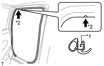
Text in Illustration *1 Paint Mark *2 Mark Position
-
Align the paint mark on the rear door opening trim with the mark position on the vehicle and install the rear door opening trim as shown in the illustration.
-
-
INSTALL REAR DOOR OPENING TRIM RH
Tech Tips
Use the same procedure described for the LH side.
-
INSTALL REAR DOOR SCUFF PLATE LH
-
Attach the 2 clips and 7 claws to install the rear door scuff plate.
-
-
INSTALL REAR DOOR SCUFF PLATE RH
Tech Tips
Use the same procedure described for the LH side.
-
INSTALL FRONT PILLAR GARNISH LH
-
w/ Curtain Shield Airbag:
-
Remove the protective cover.
-
-
Attach the 2 guides and 2 clips to install the front pillar garnish.
-
-
INSTALL FRONT PILLAR GARNISH RH
Tech Tips
Use the same procedure described for the LH side.
-
INSTALL FRONT ASSIST GRIP SUB-ASSEMBLY (w/ Assist Grip)
Tech Tips
Use the same procedure for both front assist grips.
-
Install the front assist grip with the 2 screws.
-
-
INSTALL FRONT NO. 1 ASSIST GRIP PLUG LH (w/ Assist Grip)
Tech Tips
Use the same procedure for both front No. 1 assist grip plugs.
-
Attach the 2 claws to install the front No. 1 assist grip plug.
-
-
INSTALL FRONT NO. 1 ASSIST GRIP PLUG RH (w/ Assist Grip)
Tech Tips
Use the same procedure described for the LH side.
-
INSTALL FRONT DOOR OPENING TRIM LH
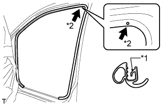
Text in Illustration *1 Paint Mark *2 Mark Position
-
Align the paint mark on the front door opening trim with the mark position on the vehicle and install the front door opening trim as shown in the illustration.
-
-
INSTALL FRONT DOOR OPENING TRIM RH
Tech Tips
Use the same procedure described for the LH side.
-
INSTALL FRONT DOOR SCUFF PLATE LH
-
Attach the 3 clips and 7 claws to install the front door scuff plate.
-
-
INSTALL FRONT DOOR SCUFF PLATE RH
Tech Tips
Use the same procedure described for the LH side.
-
INSTALL REAR SEAT ASSEMBLY
-
CONNECT CABLE TO NEGATIVE BATTERY TERMINAL (w/ Airbag System)
Note
When disconnecting the cable, some systems need to be initialized after the cable is reconnected Click here.
-
CHECK SRS WARNING LIGHT (w/ Airbag System)