WIPER AND WASHER SYSTEM, Diagnostic DTC:B1372
| DTC Code | DTC Name |
|---|---|
| B1372 | Wiper Switch Signal Mismatch between LIN and Line |
DESCRIPTION
Under normal operation, the windshield wiper motor assembly receives operation signals from the windshield wiper switch assembly via LIN communication.
The windshield wiper motor assembly and windshield wiper switch assembly are also connected via direct line in order to operate the front wipers in HI in an emergency. If the operation signals sent via LIN communication and direct line do not match, this DTC is stored.
| DTC No. | Detection Item | DTC Detection Condition | Trouble Area | Memory | DTC Output from |
|---|---|---|---|---|---|
| B1372 | Wiper Switch Signal Mismatch between LIN and Line |
Detection condition:
Malfunction Status:
Malfunction Time: |
|
○ | Windshield wiper motor assembly |
WIRING DIAGRAM
-
for LHD
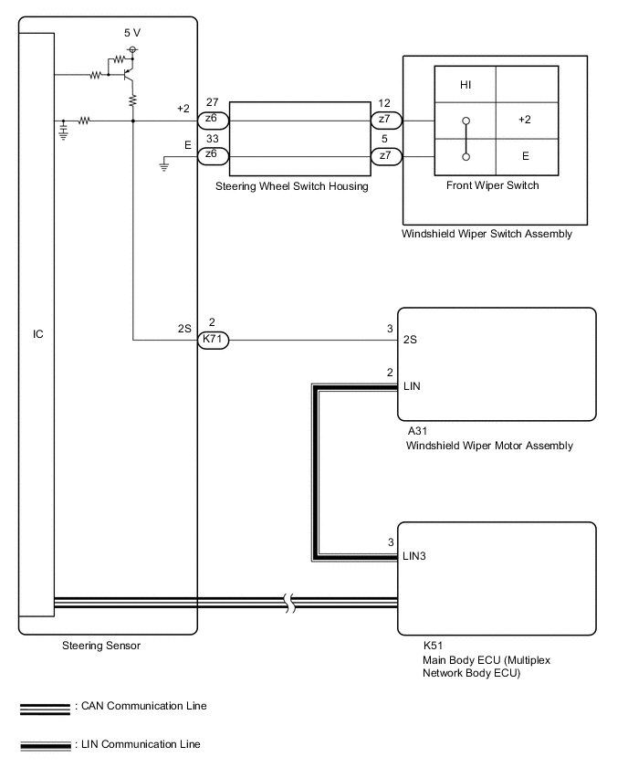
-
for RHD

CAUTION / NOTICE / HINT
Note
-
The vehicle battery supplies power to the main body ECU (multiplex network body ECU) via the door control battery. Therefore, before performing this troubleshooting procedure, make sure to perform an on-vehicle inspection to confirm that the main body ECU (multiplex network body ECU) power source circuit is normal.*1
-
Before replacing the main body ECU (multiplex network body ECU), refer to Service Bulletin.*2
-
*1: w/ Door Control Battery
-
*2: w/ Smart Entry and Start System
PROCEDURE
-
CLEAR DTC
-
Connect the GTS to the DLC3.
-
Turn the ignition switch to ON.
-
Turn the GTS on.
-
Enter the following menus: Body Electrical / Wiper / Trouble Codes.
-
Clear the DTCs.
Body Electrical > Wiper > Clear DTCsResult Proceed to NEXT
NEXT 
-
-
CHECK FOR DTC
-
Connect the GTS to the DLC3.
-
Turn the ignition switch to ON.
-
Wait 10 seconds or more.
-
Turn the GTS on.
-
Enter the following menus: Body Electrical / Wiper / Trouble Codes.
-
Check for DTCs.
Body Electrical > Wiper > Trouble CodesResult Result Proceed to DTC B1372 is not output A DTC B1372 is output B
A 
USE SIMULATION METHOD TO CHECK Click here
B
-
-
READ VALUE USING GTS
-
Connect the GTS to the DLC3.
-
Turn the ignition switch to ON.
-
Turn the GTS on.
-
Enter the following menus: Body Electrical / Wiper / Data List.
-
Read the Data List according to the display on the GTS.
Body Electrical > Wiper > Data ListTester Display Measurement Item Range Normal Condition Diagnostic Note Wiper Switch HI (Line) Front wiper switch HI position signal (direct line) OFF or ON OFF: Front wiper switch not in HI position
ON: Front wiper switch in HI position
-
Body Electrical > Wiper > Data ListTester Display Wiper Switch HI (Line) OK The GTS display is normal. Result Result OK NG
NG 
CHECK HARNESS AND CONNECTOR (STEERING SENSOR - WINDSHIELD WIPER MOTOR ASSEMBLY) Click here
OK
-
-
READ VALUE USING GTS
-
Connect the GTS to the DLC3.
-
Turn the ignition switch to ON.
-
Turn the GTS on.
-
Enter the following menus: Chassis / Steering Angle Sensor / Data List.
-
Read the Data List according to the display on the GTS.
Chassis > Steering Angle Sensor > Data ListTester Display Measurement Item Range Normal Condition Diagnostic Note Wiper Hi Switch Front wiper switch HI position signal OFF or ON OFF: Front wiper switch not in HI position
ON: Front wiper switch in HI position
-
Chassis > Steering Angle Sensor > Data ListTester Display Wiper Hi Switch OK The GTS display is normal. Result Result OK NG
NG
REPLACE STEERING SENSOR Click here
OK
-
-
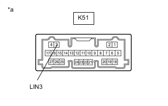
CHECK HARNESS AND CONNECTOR (MAIN BODY ECU (MULTIPLEX NETWORK BODY ECU) - WINDSHIELD WIPER MOTOR ASSEMBLY)
-
Disconnect the K51 main body ECU (multiplex network body ECU) connector.
-
Disconnect the A31 windshield wiper motor assembly connector.
-
Measure the resistance according to the value(s) in the table below.
Standard Resistance for LHD Tester Connection Condition Specified Condition K51-3 (LIN3) - A31-2 (LIN) Always Below 1 Ω K51-3 (LIN3) or A31-2 (LIN) - Body ground Always 10 kΩ Higher for RHD Tester Connection Condition Specified Condition K51-3 (LIN3) - A31-3 (LIN) Always Below 1 Ω K51-3 (LIN3) or A31-3 (LIN) - Body ground Always 10 kΩ Higher Result Proceed to OK NG
NG
REPAIR OR REPLACE HARNESS OR CONNECTOR
OK
-
-
CHECK MAIN BODY ECU (MULTIPLEX NETWORK BODY ECU)
*a Component without harness connected
(Main Body ECU (Multiplex Network Body ECU)
-
Check for voltage and pulses according to the value(s) in the table below.
Standard Voltage Tester Connection Condition Specified Condition K51-3 (LIN3) - Body ground Ignition switch off Below 1 V Ignition switch ON Pulse generation Result Proceed to OK NG
OK
REPLACE WINDSHIELD WIPER MOTOR ASSEMBLY Click here
NG
REPLACE MAIN BODY ECU (MULTIPLEX NETWORK BODY ECU) Click here
-
-
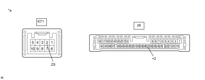
CHECK HARNESS AND CONNECTOR (STEERING SENSOR - WINDSHIELD WIPER MOTOR ASSEMBLY)
-
Disconnect the K71 steering sensor connector.
-
Disconnect the A31 windshield wiper motor assembly connector.
-
Measure the resistance according to the value(s) in the table below.
Standard Resistance for LHD Tester Connection Condition Specified Condition K71-2 (2S) - A31-3 (2S) Always Below 1 Ω K71-2 (2S) or A31-3 (2S) - Body ground Always 10 kΩ Higher for RHD Tester Connection Condition Specified Condition K71-2 (2S) - A31-2 (2S) Always Below 1 Ω K71-2 (2S) or A31-2 (2S) - Body ground Always 10 kΩ Higher Result Proceed to OK NG
NG
REPAIR OR REPLACE HARNESS OR CONNECTOR
OK
-
-
INSPECT STEERING SENSOR
*a Component without harness connected
(Steering Sensor)
- -
-
Remove the steering sensor.
-
Measure the resistance according to the value(s) in the table below.
Standard Resistance Tester Connection Condition Specified Condition K71-2 (2S) - z6-27 (+2) Always Below 1 Ω Result Proceed to OK NG
OK
REPLACE WINDSHIELD WIPER MOTOR ASSEMBLY Click here
NG
REPLACE STEERING SENSOR Click here
-