SMART ENTRY AND START SYSTEM(for Start Function), Diagnostic DTC:B2799, B279986
| DTC Code | DTC Name |
|---|---|
| B2799 | Engine Immobiliser System Malfunction |
| B279986 | Engine Immobiliser System Signal (Some Circuit Quantity, Reported via Serial Data) Invalid |
DESCRIPTION
If there is a communication malfunction between the ECM and certification ECU (smart key ECU assembly)*1 or ID code box (immobiliser code ECU)*2, or when the communication ID codes do not match, the ECM stores this DTC.
-
*1: w/o ID Code Box
-
*2: w/ ID Code Box
| DTC No. | Detection Item | DTC Detection Condition | Trouble Area | Note |
|---|---|---|---|---|
| B2799 | Engine Immobiliser System Malfunction | Either of the following conditions is met (1 trip detection logic*1):
|
|
DTC output confirmation operation (Perform either of the following):
|
| B279986 | Engine Immobiliser System Signal (Some Circuit Quantity, Reported via Serial Data) Invalid | Either of the following conditions is met (1 trip detection logic*1):
|
|
DTC output confirmation operation (Perform either of the following):
|
-
*1: Only output while a malfunction is present.
-
*2: w/o ID Code Box
-
*3: w/ ID Code Box
| Vehicle Condition when Malfunction Detected | Fail-safe Operation when Malfunction Detected |
|---|---|
| Engine cannot be started | - |
| DTC No. | Data List and Active Test |
|---|---|
| B2799*1 B279986*2 |
- |
-
*1: for 2AR-FE
-
*2: except 2AR-FE
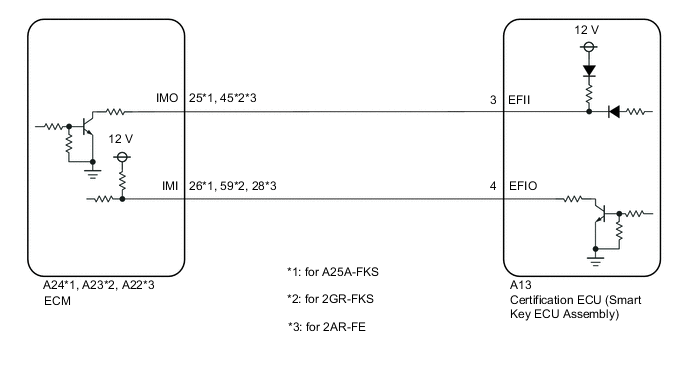
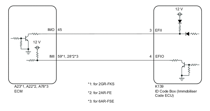
WIRING DIAGRAM
-
w/o ID Code Box
-
w/ ID Code Box
CAUTION / NOTICE / HINT
Note
-
When using the GTS with the engine switch off, connect the GTS to the DLC3 and turn a courtesy light switch on and off at intervals of 1.5 seconds or less until communication between the GTS and the vehicle begins. Then select Model Code "KEY REGIST" under manual mode and enter the following menus: Body Electrical / Entry&Start(CAN). While using the GTS, periodically turn a courtesy light switch on and off at intervals of 1.5 seconds or less to maintain communication between the GTS and the vehicle.
-
The smart entry and start system (for Start Function) uses the LIN communication system and CAN communication system. Inspect the communication function by following How to Proceed with Troubleshooting. Troubleshoot the smart entry and start system (for Start Function) after confirming that the communication systems are functioning properly.
-
Before replacing the ECM, certification ECU (smart key ECU assembly)*1 or ID code box (immobiliser code ECU)*2, refer to Service Bulletin.
-
*1: w/o ID Code Box
-
*2: w/ ID Code Box
-
After performing repairs, confirm that no DTCs are output by performing "DTC Output Confirmation Operation".
Tech Tips
When DTC B279986 and the certification ECU (smart key ECU assembly) DTC are output simultaneously, first perform troubleshooting for the certification ECU (smart key ECU assembly) DTC.
PROCEDURE
-
REGISTER ECU COMMUNICATION ID
-
Register the ECU communication ID code.
Tech Tips
Refer to Service Bulletin.
Result Result Proceed to NEXT (w/o ID Code Box) A NEXT (w/ ID Code Box) B
B 
CHECK ECM (TERMINAL EFII) Click here
A 
-
-
CHECK ECM (TERMINAL EFII)
-
Using an oscilloscope, check the waveform.
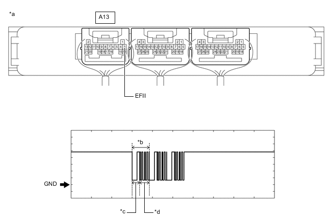
*a Component with harness connected
(Certification ECU (Smart Key ECU Assembly))
*b Waveform *c Approximately 160 ms. *d Approximately 270 ms. OK Tester Connection Condition Tool Setting Specified Condition A13-3 (EFII) - Body ground Engine switch on (IG) 2 V/DIV., 500 ms./DIV. Pulse generation
(See waveform)
Result Result Proceed to Normal waveform A Terminal EFII stuck low (2.4 V or less) B Waveform not output, or has abnormal wavelength or shape C
B
CHECK ECM Click here
C 
REPLACE ECM for A25A-FKS: Click here
REPLACE ECM for 2GR-FKS: Click here
REPLACE ECM for 2AR-FE: Click hereA
-
-
CHECK CERTIFICATION ECU (SMART KEY ECU ASSEMBLY) (TERMINAL EFIO)
-
Using an oscilloscope, check the waveform.
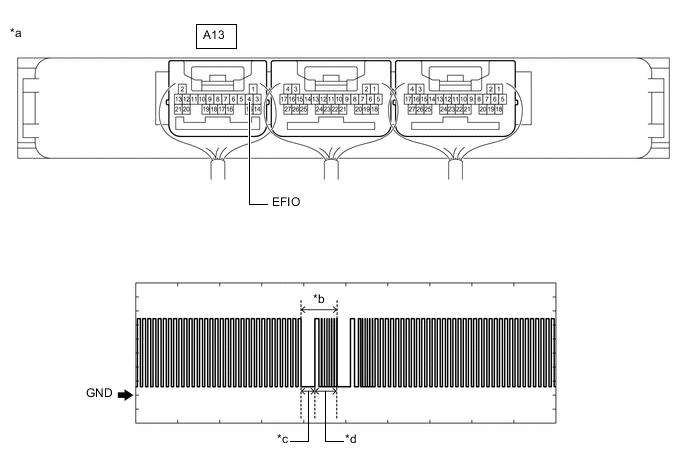
*a Component with harness connected
(Certification ECU (Smart Key ECU Assembly))
*b Waveform *c Approximately 160 ms. *d Approximately 270 ms. OK Tester Connection Condition Tool Setting Specified Condition A13-4 (EFIO) - Body ground Engine switch turned on (IG) using registered electrical key transmitter sub-assembly 2 V/DIV., 500 ms./DIV. Pulse generation
(See waveform)
Result Proceed to OK NG
NG
REPLACE CERTIFICATION ECU (SMART KEY ECU ASSEMBLY)
OK
-
-
REGISTER ECU COMMUNICATION ID
-
Register the ECU communication ID code.
Tech Tips
Refer to Service Bulletin.
Result Proceed to NEXT
NEXT
-
-
CHECK WHETHER ENGINE STARTS
-
Using an electrical key transmitter sub-assembly which is registered to the vehicle, turn the engine switch on (IG).
-
Check that the engine starts 5 seconds after the engine switch turned on (IG).
OK Engine starts normally. Result Proceed to OK NG
OK
END (ECU COMMUNICATION ID HAS NOT BEEN REGISTERED)
NG
REPLACE ECM for A25A-FKS: Click here
REPLACE ECM for 2GR-FKS: Click here
REPLACE ECM for 2AR-FE: Click here -
-
CHECK ECM
-
Disconnect the A24*1, A23*2 or A22*3 ECM connector.
-
*1: for A25A-FKS
-
*2: for 2GR-FKS
-
*3: for 2AR-FE
-
-
Measure the voltage according to the value(s) in the table below.
Standard Voltage for A25A-FKS Tester Connection Condition Specified Condition A24-25 (IMO) - Body ground Engine switch turned on (IG) using registered electrical key transmitter sub-assembly Terminal IMO stuck low (2.4 V or less) Terminal IMO stuck high (12 V) or abnormal waveform for 2GR-FKS Tester Connection Condition Specified Condition A23-45 (IMO) - Body ground Engine switch turned on (IG) using registered electrical key transmitter sub-assembly Terminal IMO stuck low (2.4 V or less) Terminal IMO stuck high (12 V) or abnormal waveform for 2AR-FE Tester Connection Condition Specified Condition A22-45 (IMO) - Body ground Engine switch turned on (IG) using registered electrical key transmitter sub-assembly Terminal IMO stuck low (2.4 V or less) Terminal IMO stuck high (12 V) or abnormal waveform Result Result Proceed to Terminal IMO stuck low (2.4 V or less) A Terminal IMO stuck high (12 V) or abnormal waveform B
B
REPLACE ECM for A25A-FKS: Click here
REPLACE ECM for 2GR-FKS: Click here
REPLACE ECM for 2AR-FE: Click hereA
-
-
CHECK HARNESS AND CONNECTOR (CERTIFICATION ECU (SMART KEY ECU ASSEMBLY) - ECM)
-
Disconnect the A13 certification ECU (smart key ECU assembly) connector.
-
Measure the resistance according to the value(s) in the table below.
Standard Resistance for A25A-FKS Tester Connection Condition Specified Condition A13-3 (EFII) - A24-25 (IMO) Always Below 1 Ω A13-3 (EFII) or A24-25 (IMO) - Other terminals and body ground Always 10 kΩ or higher for 2GR-FKS Tester Connection Condition Specified Condition A13-3 (EFII) - A23-45 (IMO) Always Below 1 Ω A13-3 (EFII) or A23-45 (IMO) - Other terminals and body ground Always 10 kΩ or higher for 2AR-FE Tester Connection Condition Specified Condition A13-3 (EFII) - A22-45 (IMO) Always Below 1 Ω A13-3 (EFII) or A22-45 (IMO) - Other terminals and body ground Always 10 kΩ or higher Result Proceed to OK NG
OK
REPLACE CERTIFICATION ECU (SMART KEY ECU ASSEMBLY)
NG
REPAIR OR REPLACE HARNESS OR CONNECTOR
-
-
CHECK ECM (TERMINAL EFII)
-
Using an oscilloscope, check the waveform.
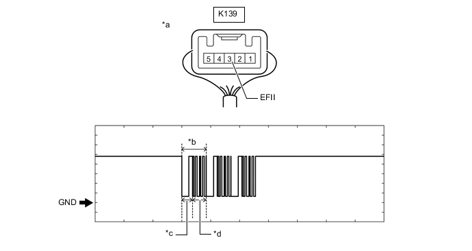
*a Component with harness connected
(ID Code Box (Immobiliser Code ECU))
*b Waveform *c Approximately 160 ms. *d Approximately 270 ms. OK Tester Connection Condition Tool Setting Specified Condition K139-3 (EFII) - Body ground Engine switch on (IG) 2 V/DIV., 500 ms./DIV. Pulse generation
(See waveform)
Result Result Proceed to Normal waveform A Terminal IMO stuck low (2.4 V or less) B Waveform not output, or has abnormal wavelength or shape C
B
CHECK ECM Click here
C
REPLACE ECM for 2GR-FKS: Click here
REPLACE ECM for 2AR-FE: Click here
REPLACE ECM for 6AR-FSE: Click hereA
-
-
CHECK ID CODE BOX (IMMOBILISER CODE ECU) (TERMINAL EFIO)
-
Using an oscilloscope, check the waveform.
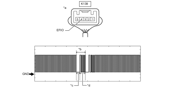
*a Component with harness connected
(ID Code Box (Immobiliser Code ECU))
*b Waveform *c Approximately 160 ms. *d Approximately 270 ms. Measurement Condition Tester Connection Condition Tool Setting Specified Condition K139-4 (EFIO) - Body ground Engine switch turned on (IG) using registered electrical key transmitter sub-assembly 2 V/DIV., 500 ms./DIV. Pulse generation
(See waveform)
Result Proceed to OK NG
NG
REPLACE ID CODE BOX (IMMOBILISER CODE ECU)
OK
-
-
REGISTER ECU COMMUNICATION ID (ID CODE BOX (IMMOBILISER CODE ECU) - ECM)
-
Register the ECU communication ID codes.
Tech Tips
Refer to Service Bulletin.
Result Proceed to NEXT
NEXT
-
-
CHECK WHETHER ENGINE STARTS
-
Using an electrical key transmitter sub-assembly which is registered to the vehicle, turn the engine switch on (IG).
-
Check that the engine can be started 5 seconds after the engine switch turned on (IG).
OK Engine starts normally. Result Proceed to OK NG
OK
END (ECU COMMUNICATION ID HAS NOT BEEN REGISTERED)
NG
REPLACE ECM for 2GR-FKS: Click here
REPLACE ECM for 2AR-FE: Click here
REPLACE ECM for 6AR-FSE: Click here -
-
CHECK ECM
-
Disconnect the A23*1, A22*2 or A78*3 ECM connector.
-
*1: for 2GR-FKS
-
*2: for 2AR-FE
-
*3: for 6AR-FSE
-
-
Measure the voltage according to the value(s) in the table below.
Standard Voltage for 2GR-FKS Tester Connection Condition Specified Condition A23-45 (IMO) - Body ground Engine switch turned on (IG) using registered electrical key transmitter sub-assembly Terminal IMO stuck low (2.4 V or less) Terminal IMO stuck high (12 V) or abnormal waveform for 2AR-FE Tester Connection Condition Specified Condition A22-45 (IMO) - Body ground Engine switch turned on (IG) using registered electrical key transmitter sub-assembly Terminal IMO stuck low (2.4 V or less) Terminal IMO stuck high (12 V) or abnormal waveform for 6AR-FSE Tester Connection Condition Specified Condition A78-45 (IMO) - Body ground Engine switch turned on (IG) using registered electrical key transmitter sub-assembly Terminal IMO stuck low (2.4 V or less) Terminal IMO stuck high (12 V) or abnormal waveform Result Result Proceed to Terminal IMO stuck low (2.4 V or less) A Terminal IMO stuck high (12 V) or abnormal waveform B
B
REPLACE ECM for 2GR-FKS: Click here
REPLACE ECM for 2AR-FE: Click here
REPLACE ECM for 6AR-FSE: Click hereA
-
-
CHECK HARNESS AND CONNECTOR (ID CODE BOX (IMMOBILISER CODE ECU) - ECM)
-
Disconnect the K139 ID code box (immobiliser code ECU) connector.
-
Measure the resistance according to the value(s) in the table below.
Standard Resistance for 2GR-FKS Tester Connection Condition Specified Condition K139-3 (EFII) - A23-45 (IMO) Always Below 1 Ω K139-3 (EFII) or A23-45 (IMO) - Other terminals and body ground Always 10 kΩ or higher for 2AR-FE Tester Connection Condition Specified Condition K139-3 (EFII) - A22-45 (IMO) Always Below 1 Ω K139-3 (EFII) or A22-45 (IMO) - Other terminals and body ground Always 10 kΩ or higher for 6AR-FSE Tester Connection Condition Specified Condition K139-3 (EFII) - A78-45 (IMO) Always Below 1 Ω K139-3 (EFII) or A78-45 (IMO) - Other terminals and body ground Always 10 kΩ or higher Result Proceed to OK NG
OK
REPLACE ID CODE BOX (IMMOBILISER CODE ECU)
NG
REPAIR OR REPLACE HARNESS OR CONNECTOR
-