NAVIGATION SYSTEM TV Screen is Distorted
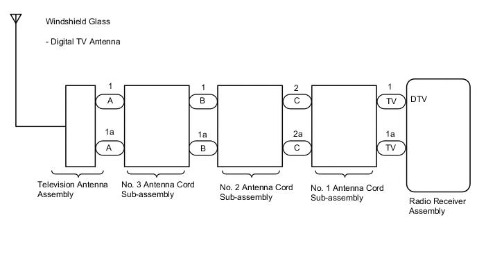
WIRING DIAGRAM
PROCEDURE
-
CHECK OPTIONAL COMPONENTS
-
Check if any optional components that may decrease reception capacity, such as sunshade film or a telephone antenna, are installed.
Result Result Proceed to Optional components are not installed A Optional components are installed B Note
Do not remove optional components without the permission of the customer.
B 
REMOVE OPTIONAL COMPONENTS AND CHECK AGAIN (SEE NOTICE ABOVE)
A 
-
-
CHECK WINDSHIELD GLASS (DIGITAL TV ANTENNA)
-
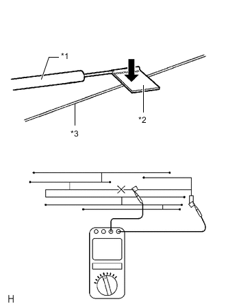
*1 Tester Probe *2 Tin Foil *3 Antenna Wire Check for continuity in the antenna.
Tech Tips
Check for continuity at the center of each antenna wire as shown in the illustration.
Note
When cleaning the glass, wipe it in the direction of the wire with a soft dry cloth. Take care not to damage the wire. Do not use detergents or glass cleaners with abrasive ingredients. When measuring resistance, wrap a piece of tin foil around the tip of each probe and press the foil against the wire with your finger as shown in the illustration.
OK There is continuity in the antenna wire. Result Proceed to OK NG
NG
REPAIR WINDSHIELD GLASS (DIGITAL TV ANTENNA)
OK
-
-
CHECK DTV RECEPTION CHECK (OPERATION CHECK)
-
Enter the "DTV reception check" screen. Refer to Check Digital Television Reception in Operation Check.
Tech Tips
-
As digital TV is a terrestrial broadcast, the digital TV antenna cannot receive the signal in places where the signal may not reach the vehicle, such as mountains or tunnels.
-
Even in areas where digital TV broadcasts for households can be received, the in-vehicle digital TV may not be able to receive the broadcast.
-
-
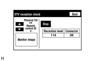
Check the digital TV tuner reception level.
Tech Tips
-
Do not depend solely on the reception level as a reference value as it may vary depending on the signal conditions such as wave interference.
-
If the result changes after turning around the vehicle, it is not a malfunction, but is caused by a local weak electric field.
OK Digital TV tuner reception level check result indicates good reception. Result Proceed to OK NG -
OK
REPLACE RADIO RECEIVER ASSEMBLY Click here
NG
-
-
CHECK NO. 3 ANTENNA CORD SUB-ASSEMBLY
-
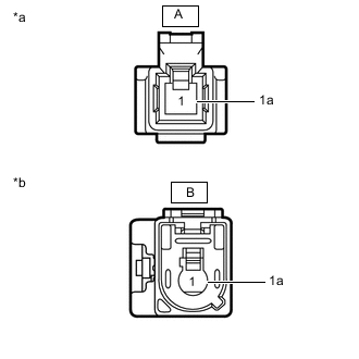
*a Front view of wire harness connector
(to Television Antenna Assembly)
*b Front view of wire harness connector
(to No. 2 Antenna Cord Sub-assembly)
Remove the antenna connector from the television antenna assembly.
-
Remove the antenna connector from the No. 2 antenna cord sub-assembly.
-
Measure the resistance according to the value(s) in the table below.
Standard Resistance Tester Connection Condition Specified Condition A-1 - B-1 Always Below 1 Ω A-1a - B-1a Always Below 1 Ω A-1 - Body ground Always 10 kΩ or higher A-1a - Body ground Always 10 kΩ or higher Result Proceed to OK NG
NG
REPLACE NO. 3 ANTENNA CORD SUB-ASSEMBLY Click here
OK
-
-
CHECK NO. 2 ANTENNA CORD SUB-ASSEMBLY
-
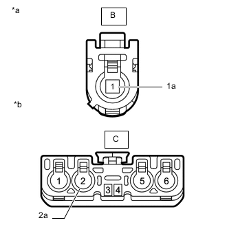
*a Front view of wire harness connector
(to No. 3 Antenna Cord Sub-assembly)
*b Front view of wire harness connector
(to No. 1 Antenna Cord Sub-assembly)
Remove the antenna connector from the No. 3 antenna cord sub-assembly.
-
Remove the antenna connector from the No. 1 antenna cord sub-assembly.
-
Measure the resistance according to the value(s) in the table below.
Standard Resistance Tester Connection Condition Specified Condition B-1 - C-2 Always Below 1 Ω B-1a - C-2a Always Below 1 Ω B-1 - Body ground Always 10 kΩ or higher B-1a - Body ground Always 10 kΩ or higher Result Proceed to OK NG
NG
REPLACE NO. 2 ANTENNA CORD SUB-ASSEMBLY Click here
OK
-
-
CHECK NO. 1 ANTENNA CORD SUB-ASSEMBLY
-
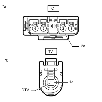
*a Front view of wire harness connector
(to No. 2 Antenna Cord Sub-assembly)
*b Front view of wire harness connector
(to Radio Receiver Assembly)
Remove the antenna connector from the No. 2 antenna cord sub-assembly.
-
Remove the antenna connector from the radio receiver assembly.
-
Measure the resistance according to the value(s) in the table below.
Standard Resistance Tester Connection Condition Specified Condition C-2 - TV-1 (DTV) Always Below 1 Ω C-2a - TV-1a Always Below 1 Ω C-2 - Body ground Always 10 kΩ or higher C-2a - Body ground Always 10 kΩ or higher Result Proceed to OK NG
NG
REPLACE NO. 1 ANTENNA CORD SUB-ASSEMBLY Click here
OK
-
-
CHECK TELEVISION ANTENNA ASSEMBLY
-
Replace the television antenna assembly.
-
Check if the same problem occurs again.
OK Malfunction does not disappears. Result Proceed to OK NG
OK
END (TELEVISION ANTENNA ASSEMBLY IS DEFECTIVE)
NG
-
-
CHECK WINDSHIELD GLASS (DIGITAL TV ANTENNA)
-
Replace the windshield glass (digital TV antenna).
-
Check if the same problem occurs again.
OK Malfunction does not disappears. Result Proceed to OK NG
OK
END (WINDSHIELD GLASS [DIGITAL TV ANTENNA] IS DEFECTIVE)
NG
REPLACE RADIO RECEIVER ASSEMBLY Click here
-