METER / GAUGE SYSTEM, Diagnostic DTC:B1507 and B1508
| DTC Code | DTC Name |
|---|---|
| B1507 | Open in Turn Signal Circuit |
| B1508 | Short in Turn Signal / Hazard Flasher Circuit |
DESCRIPTION
These DTCs are stored when the combination meter assembly detects an open in a turn signal light circuit, or a short in a turn signal light circuit or the hazard warning light circuit.
DTC No. |
Detection Item |
DTC Detection Condition |
Trouble Area |
Memory |
Note |
|---|---|---|---|---|---|
B1507 |
Open in Turn Signal Circuit |
When IG voltage is 9.5 V or more and the following condition is detected:
|
|
DTC stored |
- |
B1508 |
Short in Turn Signal / Hazard Flasher Circuit |
When IG voltage is 9.5 V or more and the following condition is detected:
|
|
DTC stored |
- |
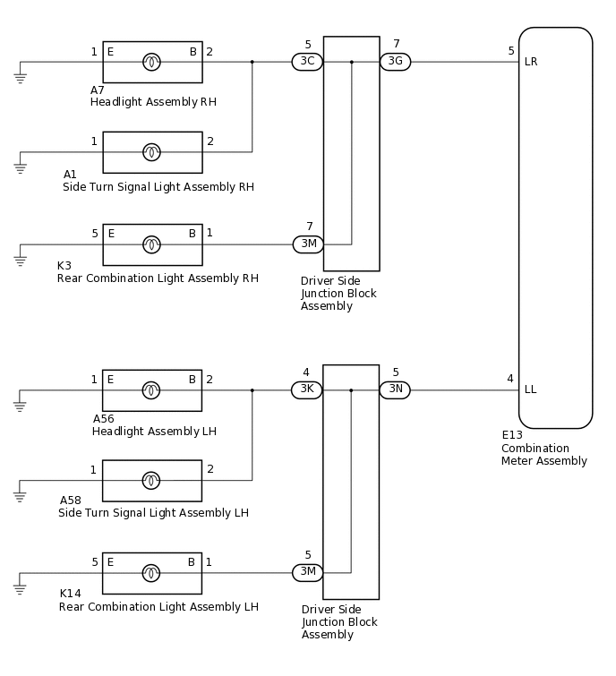
WIRING DIAGRAM
CAUTION / NOTICE / HINT
Inspect the bulbs for this system before performing the following procedure.
Side turn signal light assembly:Click here
When it is necessary to replace the combination meter assembly, be sure to replace it with a new one.
PROCEDURE
INSPECT LIGHTS
Inspect the illumination of each turn signal light.
Result
Result
Proceed to
All RH turn signal lights or all LH turn signal lights do not blink.
A
RH side turn signal light does not illuminate.
B
LH side turn signal light does not illuminate.
C
CHECK HARNESS AND CONNECTOR (COMBINATION METER ASSEMBLY - DRIVER SIDE JUNCTION BLOCK ASSEMBLY OR BODY GROUND)
Disconnect the E13 combination meter assembly connector.
RH side
Disconnect the 3G driver side junction block assembly connectors.
Measure the resistance according to the value(s) in the table below.
Standard Resistance (Check for Open)
Tester Connection
Condition
Specified Condition
E13-5 (LR) - 3G-7
Always
Below 1 Ω
Standard Resistance (Check for Short)
Tester Connection
Condition
Specified Condition
E13-5 (LR) - Body ground
Always
10 kΩ or higher
LH side
Disconnect the 3N driver side junction block assembly connectors.
Measure the resistance according to the value(s) in the table below.
Standard Resistance (Check for Open)
Tester Connection
Condition
Specified Condition
E13-4 (LL) - 3N-5
Always
Below 1 Ω
Standard Resistance (Check for Short)
Tester Connection
Condition
Specified Condition
E13-4 (LL) - Body ground
Always
10 kΩ or higher
Result
Proceed to
OK
NG
NG REPAIR OR REPLACE HARNESS OR CONNECTOR
INSPECT DRIVER SIDE JUNCTION BLOCK ASSEMBLY
Remove the driver side junction block assembly.
Measure the resistance according to the value(s) in the table below.
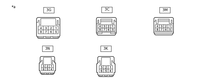
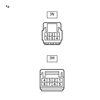
*a
Component without harness connected
(Driver Side Junction Block Assembly)
-
-
RH side
Standard Resistance
Tester Connection
Condition
Specified Condition
3G-7 - 3C-5
Always
Below 1 Ω
3G-7 - 3M-7
Always
Below 1 Ω
LH side
Standard Resistance
Tester Connection
Condition
Specified Condition
3N-5 - 3K-4
Always
Below 1 Ω
3N-5 - 3M-5
Always
Below 1 Ω
Result
Proceed to
OK
NG
CHECK TURN SIGNAL LIGHTS (RH SIDE)
Turn the ignition switch to ON.
Set the headlight dimmer switch assembly to the right turn switch position.
Check the operation of the turn signal lights.
Result
Result
Proceed to
Front turn signal light RH does not blink.
A
Side turn signal light assembly RH does not blink.
B
Rear turn signal light RH does not blink.
C
Front turn signal light RH and side turn signal light assembly RH do not blink.
D
B CHECK HARNESS AND CONNECTOR (SIDE TURN SIGNAL LIGHT ASSEMBLY RH - DRIVER SIDE JUNCTION BLOCK ASSEMBLY OR BODY GROUND)Click here
C CHECK HARNESS AND CONNECTOR (REAR COMBINATION LIGHT ASSEMBLY RH - DRIVER SIDE JUNCTION BLOCK ASSEMBLY OR BODY GROUND)Click here
D CHECK HARNESS AND CONNECTOR (HEADLIGHT ASSEMBLY RH AND SIDE TURN SIGNAL LIGHT ASSEMBLY RH - DRIVER SIDE JUNCTION BLOCK ASSEMBLY OR BODY GROUND)Click here
CHECK HARNESS AND CONNECTOR (HEADLIGHT ASSEMBLY RH - DRIVER SIDE JUNCTION BLOCK ASSEMBLY OR BODY GROUND)
Disconnect the A7 headlight assembly RH connector.
Disconnect the A1 side turn signal light assembly RH connector.
Disconnect the 3C driver side junction block assembly connector.
Measure the resistance according to the value(s) in the table below.
Standard Resistance (Check for Open)
Tester Connection
Condition
Specified Condition
A7-2 (B) - 3C-5
Always
Below 1 Ω
A7-1 (E) - Body ground
Always
Below 1 Ω
Standard Resistance (Check for Short)
Tester Connection
Condition
Specified Condition
3C-5 - Body ground
Always
10 kΩ or higher
Result
Proceed to
OK
NG
NG REPAIR OR REPLACE HARNESS OR CONNECTOR
INSPECT DRIVER SIDE JUNCTION BLOCK ASSEMBLY
Remove the driver side junction block assembly.
-
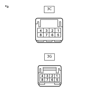
*a
Component without harness connected
(Driver Side Junction Block Assembly)
Measure the resistance according to the value(s) in the table below.
Standard Resistance
Tester Connection
Condition
Specified Condition
3G-7 - 3C-5
Always
Below 1 Ω
Result
Proceed to
OK
NG
CHECK HARNESS AND CONNECTOR (SIDE TURN SIGNAL LIGHT ASSEMBLY RH - DRIVER SIDE JUNCTION BLOCK ASSEMBLY OR BODY GROUND)
Disconnect the A1 side turn signal light assembly RH connector.
Disconnect the A7 headlight assembly RH connector.
Disconnect the 3C driver side junction block assembly connector.
Measure the resistance according to the value(s) in the table below.
Standard Resistance (Check for Open)
Tester Connection
Condition
Specified Condition
A1-2 - 3C-5
Always
Below 1 Ω
A1-1 - Body ground
Always
Below 1 Ω
Standard Resistance (Check for Short)
Tester Connection
Condition
Specified Condition
3C-5 - Body ground
Always
10 kΩ or higher
Result
Proceed to
OK
NG
NG REPAIR OR REPLACE HARNESS OR CONNECTOR
INSPECT DRIVER SIDE JUNCTION BLOCK ASSEMBLY
Remove the driver side junction block assembly.
-
*a
Component without harness connected
(Driver Side Junction Block Assembly)
Measure the resistance according to the value(s) in the table below.
Standard Resistance
Tester Connection
Condition
Specified Condition
3G-7 - 3C-5
Always
Below 1 Ω
Result
Proceed to
OK
NG
CHECK HARNESS AND CONNECTOR (REAR COMBINATION LIGHT ASSEMBLY RH - DRIVER SIDE JUNCTION BLOCK ASSEMBLY OR BODY GROUND)
Disconnect the K3 rear combination light assembly RH connector.
Disconnect the 3M driver side junction block assembly connector.
Measure the resistance according to the value(s) in the table below.
Standard Resistance (Check for Open)
Tester Connection
Condition
Specified Condition
K3-1 (B) - 3M-7
Always
Below 1 Ω
K3-5 (E) - Body ground
Always
Below 1 Ω
Standard Resistance (Check for Short)
Tester Connection
Condition
Specified Condition
3M-7 - Body ground
Always
10 kΩ or higher
Result
Proceed to
OK
NG
NG REPAIR OR REPLACE HARNESS OR CONNECTOR
INSPECT DRIVER SIDE JUNCTION BLOCK ASSEMBLY
Remove the driver side junction block assembly.
-

*a
Component without harness connected
(Driver Side Junction Block Assembly)
Measure the resistance according to the value(s) in the table below.
Standard Resistance
Tester Connection
Condition
Specified Condition
3G-7 - 3M-7
Always
Below 1 Ω
Result
Proceed to
OK
NG
CHECK HARNESS AND CONNECTOR (HEADLIGHT ASSEMBLY RH AND SIDE TURN SIGNAL LIGHT ASSEMBLY RH - DRIVER SIDE JUNCTION BLOCK ASSEMBLY OR BODY GROUND)
Disconnect the A7 headlight assembly RH connector.
Disconnect the A1 side turn signal light assembly RH connector.
Disconnect the 3C driver side junction block assembly connector.
Measure the resistance according to the value(s) in the table below.
Standard Resistance (Check for Open)
Tester Connection
Condition
Specified Condition
A7-2 (B) - 3C-5
Always
Below 1 Ω
A1-2 - 3C-5
Always
Below 1 Ω
Standard Resistance (Check for Short)
Tester Connection
Condition
Specified Condition
3C-5 - Body ground
Always
10 kΩ or higher
Result
Proceed to
OK
NG
NG REPAIR OR REPLACE HARNESS OR CONNECTOR
INSPECT DRIVER SIDE JUNCTION BLOCK ASSEMBLY
Remove the driver side junction block assembly.
-
*a
Component without harness connected
(Driver Side Junction Block Assembly)
Measure the resistance according to the value(s) in the table below.
Standard Resistance
Tester Connection
Condition
Specified Condition
3G-7 - 3C-5
Always
Below 1 Ω
Result
Proceed to
OK
NG
CHECK TURN SIGNAL LIGHTS (LH SIDE)
Turn the ignition switch to ON.
Set the headlight dimmer switch assembly to the left turn switch position.
Check the operation of the turn signal lights.
Result
Result
Proceed to
Front turn signal light LH does not blink.
A
Side turn signal light assembly LH does not blink.
B
Rear turn signal light LH does not blink.
C
Front turn signal light LH and side turn signal light assembly LH do not blink.
D
B CHECK HARNESS AND CONNECTOR (SIDE TURN SIGNAL LIGHT ASSEMBLY LH - DRIVER SIDE JUNCTION BLOCK ASSEMBLY OR BODY GROUND)Click here
C CHECK HARNESS AND CONNECTOR (REAR COMBINATION LIGHT ASSEMBLY LH - DRIVER SIDE JUNCTION BLOCK ASSEMBLY OR BODY GROUND)Click here
D CHECK HARNESS AND CONNECTOR (HEADLIGHT ASSEMBLY LH AND SIDE TURN SIGNAL LIGHT ASSEMBLY LH - DRIVER SIDE JUNCTION BLOCK ASSEMBLY OR BODY GROUND)Click here
CHECK HARNESS AND CONNECTOR (HEADLIGHT ASSEMBLY LH - DRIVER SIDE JUNCTION BLOCK ASSEMBLY OR BODY GROUND)
Disconnect the A56 headlight assembly LH connector.
Disconnect the A58 side turn signal light assembly LH connector.
Disconnect the 3K driver side junction block assembly connector.
Measure the resistance according to the value(s) in the table below.
Standard Resistance (Check for Open)
Tester Connection
Condition
Specified Condition
A56-2 (B) - 3K-4
Always
Below 1 Ω
A56-1 (E) - Body ground
Always
Below 1 Ω
Standard Resistance (Check for Short)
Tester Connection
Condition
Specified Condition
3K-4 - Body ground
Always
10 kΩ or higher
Result
Proceed to
OK
NG
NG REPAIR OR REPLACE HARNESS OR CONNECTOR
INSPECT DRIVER SIDE JUNCTION BLOCK ASSEMBLY
Remove the driver side junction block assembly.
-
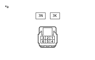
*a
Component without harness connected
(Driver Side Junction Block Assembly)
Measure the resistance according to the value(s) in the table below.
Standard Resistance
Tester Connection
Condition
Specified Condition
3N-5 - 3K-4
Always
Below 1 Ω
Result
Proceed to
OK
NG
CHECK HARNESS AND CONNECTOR (SIDE TURN SIGNAL LIGHT ASSEMBLY LH - DRIVER SIDE JUNCTION BLOCK ASSEMBLY OR BODY GROUND)
Disconnect the A58 side turn signal light assembly LH connector.
Disconnect the A56 headlight assembly LH connector.
Disconnect the 3K driver side junction block assembly connector.
Measure the resistance according to the value(s) in the table below.
Standard Resistance (Check for Open)
Tester Connection
Condition
Specified Condition
A58-2 - 3K-4
Always
Below 1 Ω
A58-1 - Body ground
Always
Below 1 Ω
Standard Resistance (Check for Short)
Tester Connection
Condition
Specified Condition
3K-4 - Body ground
Always
10 kΩ or higher
Result
Proceed to
OK
NG
NG REPAIR OR REPLACE HARNESS OR CONNECTOR
INSPECT DRIVER SIDE JUNCTION BLOCK ASSEMBLY
Remove the driver side junction block assembly.
-
*a
Component without harness connected
(Driver Side Junction Block Assembly)
Measure the resistance according to the value(s) in the table below.
Standard Resistance
Tester Connection
Condition
Specified Condition
3N-5 - 3K-4
Always
Below 1 Ω
Result
Proceed to
OK
NG
CHECK HARNESS AND CONNECTOR (REAR COMBINATION LIGHT ASSEMBLY LH - DRIVER SIDE JUNCTION BLOCK ASSEMBLY OR BODY GROUND)
Disconnect the K14 rear combination light assembly LH connector.
Disconnect the 3M driver side junction block assembly connector.
Measure the resistance according to the value(s) in the table below.
Standard Resistance (Check for Open)
Tester Connection
Condition
Specified Condition
K14-1 (B) - 3M-5
Always
Below 1 Ω
K14-5 (E) - Body ground
Always
Below 1 Ω
Standard Resistance (Check for Short)
Tester Connection
Condition
Specified Condition
3M-5 - Body ground
Always
10 kΩ or higher
Result
Proceed to
OK
NG
NG REPAIR OR REPLACE HARNESS OR CONNECTOR
INSPECT DRIVER SIDE JUNCTION BLOCK ASSEMBLY
Remove the driver side junction block assembly.
-
*a
Component without harness connected
(Driver Side Junction Block Assembly)
Measure the resistance according to the value(s) in the table below.
Standard Resistance
Tester Connection
Condition
Specified Condition
3N-5 - 3M-5
Always
Below 1 Ω
Result
Proceed to
OK
NG
CHECK HARNESS AND CONNECTOR (HEADLIGHT ASSEMBLY LH AND SIDE TURN SIGNAL LIGHT ASSEMBLY LH - DRIVER SIDE JUNCTION BLOCK ASSEMBLY OR BODY GROUND)
Disconnect the A56 headlight assembly LH connector.
Disconnect the A58 side turn signal light assembly LH connector.
Disconnect the 3K driver side junction block assembly connector.
Measure the resistance according to the value(s) in the table below.
Standard Resistance (Check for Open)
Tester Connection
Condition
Specified Condition
A56-2 (B) - 3K-4
Always
Below 1 Ω
A58-2 - 3K-4
Always
Below 1 Ω
Standard Resistance (Check for Short)
Tester Connection
Condition
Specified Condition
3K-4 - Body ground
Always
10 kΩ or higher
Result
Proceed to
OK
NG
NG REPAIR OR REPLACE HARNESS OR CONNECTOR
INSPECT DRIVER SIDE JUNCTION BLOCK ASSEMBLY
Remove the driver side junction block assembly.
-
*a
Component without harness connected
(Driver Side Junction Block Assembly)
Measure the resistance according to the value(s) in the table below.
Standard Resistance
Tester Connection
Condition
Specified Condition
3N-5 - 3K-4
Always
Below 1 Ω
Result
Proceed to
OK
NG