CAN COMMUNICATION SYSTEM TERMINALS OF ECU
After turning the ignition switch off, waiting time may be required before disconnecting the cable from the negative (-) battery terminal. Therefore, make sure to read the disconnecting the cable from the negative (-) battery terminal notices before proceeding with work.
Turn the ignition switch off before measuring the resistances between CAN main bus lines and between CAN branch lines.
Turn the ignition switch off before inspecting CAN bus lines for a ground short.
Before measuring the resistance of the CAN bus, turn the ignition switch off and leave the vehicle for 1 minute or more without operating the key or switches, or opening or closing the doors. After that, disconnect the cable from the negative (-) battery terminal and leave the vehicle for 1 minute or more before measuring the resistance.
This section describes the standard values for all CAN related components.
Operating the ignition switch, any other switches or a door triggers related ECU and sensor communication on the CAN. This communication will cause the resistance value to change.
Even after DTCs are cleared, if a DTC is stored again after driving the vehicle for a while, the malfunction may be occurring due to vibration of the vehicle. In such a case, wiggling the ECUs or wire harness while performing the inspection below may help determine the cause of the malfunction.
NO. 1 CAN JUNCTION CONNECTOR (ENGINE ROOM MAIN WIRE)
Check the A59 No. 1 CAN junction connector.
Connection diagram
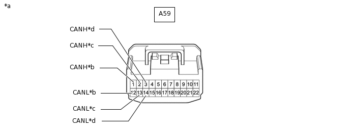
*a
Front view of wire harness connector
(to No. 1 CAN Junction Connector)
*b
to ECM
*c
to Skid Control ECU (Brake Actuator Assembly)
*d
to Engine Stop and Start ECU
(w/ Stop and Start System)
Check the connection diagram of the components which are connected to the No. 1 CAN junction connector.
Terminal No. (Symbol)
Wiring Color
Connected to
A59-1 (CANH)
B
ECM
A59-12 (CANL)
W
A59-2 (CANH)
V
Skid control ECU (brake actuator assembly)
A59-13 (CANL)
W
A59-3 (CANH)
P
Engine stop and start ECU*
A59-14 (CANL)
W
*: w/ Stop and Start System
NO. 1 CAN JUNCTION CONNECTOR (INSTRUMENT PANEL WIRE)
Check the E2 No. 1 CAN junction connector.
Connection diagram
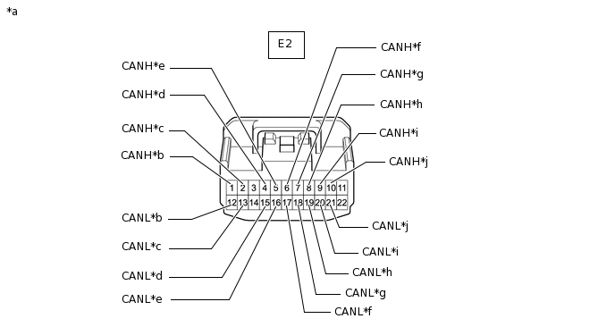
*a
Front view of wire harness connector
(to No. 1 CAN Junction Connector)
*b
to Airbag Sensor Assembly
*c
to Radio and Display Receiver Assembly
(for Radio and Display Type)
*d
to Combination Meter Assembly
*e
to Air Conditioning Control Assembly
(for Automatic Air Conditioning System)
*f
to Power Steering ECU Assembly
*g
to Steering Sensor (Spiral Cable Sub-assembly)
(w/ VSC)
*h
to DLC3
*i
to Certification ECU (Smart Key ECU Assembly)
(w/ Entry and Start System)
*j
to Pre-crash Safety City Sensor
(w/ Toyota Safety Sense)
Check the connection diagram of the components which are connected to the No. 1 CAN junction connector.
Terminal No. (Symbol)
Wiring Color
Connected to
E2-1 (CANH)
V
Airbag sensor assembly
E2-12 (CANL)
W
E2-2 (CANH)
G
Radio and display receiver assembly*1
E2-13 (CANL)
W
E2-4 (CANH)
LG
Combination meter assembly
E2-15 (CANL)
W
E2-5 (CANH)
Y
Air conditioning control assembly*2
E2-16 (CANL)
W
E2-6 (CANH)
GR
Power steering ECU assembly
E2-17 (CANL)
W
E2-7 (CANH)
SB
Steering sensor (spiral cable sub-assembly)*3
E2-18 (CANL)
W
E2-8 (CANH)
BE
DLC3
E2-19 (CANL)
W
E2-9 (CANH)
R
Certification ECU (smart key ECU assembly)*4
E2-20 (CANL)
W
E2-10 (CANH)
B
Pre-crash safety city sensor*5
E2-21 (CANL)
W
*1: for Radio and Display Type
*2: for Automatic Air Conditioning System
*3: w/ VSC
*4: w/ Entry and Start System
*5: w/ Toyota Safety Sense
DLC3
Disconnect the cable from the negative (-) battery terminal.
Measure the resistance according to the value(s) in the table below.
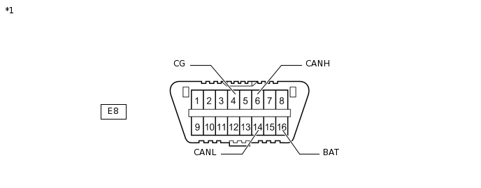
*1
DLC3
-
-
Standard Resistance
Terminal No. (Symbol)
Wiring Color
Terminal Description
Condition
Specified Condition
E8-6 (CANH) - E8-14 (CANL)
BE - W
HIGH-level CAN bus line - LOW-level CAN bus line
Cable disconnected from negative (-) battery terminal
54 to 69 Ω
E8-6 (CANH) - E8-4 (CG)
BE - W-B
HIGH-level CAN bus line - Ground
Cable disconnected from negative (-) battery terminal
200 Ω or higher
E8-14 (CANL) - E8-4 (CG)
W - W-B
LOW-level CAN bus line - Ground
Cable disconnected from negative (-) battery terminal
200 Ω or higher
E8-6 (CANH) - E8-16 (BAT)
BE - GR
HIGH-level CAN bus line - Battery positive (+)
Cable disconnected from negative (-) battery terminal
6 kΩ or higher
E8-14 (CANL) - E8-16 (BAT)
W - GR
LOW-level CAN bus line - Battery positive (+)
Cable disconnected from negative (-) battery terminal
6 kΩ or higher
ECM (for 1KR-FE)
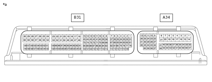
*a
Component without harness connected
(ECM)
-
-
Disconnect the cable from the negative (-) battery terminal.
Disconnect the A34 ECM connector.
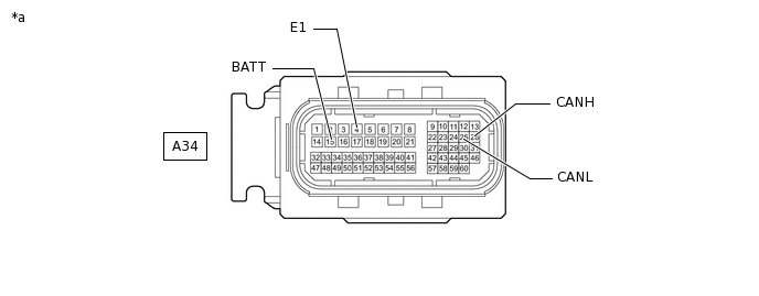
*a
Front view of wire harness connector
(to ECM)
-
-
Measure the resistance according to the value(s) in the table below.
Standard Resistance
Terminal No. (Symbol)
Wiring Color
Terminal Description
Condition
Specified Condition
A34-26 (CANH) - A34-25 (CANL)
B - W
HIGH-level CAN bus line - LOW-level CAN bus line
Cable disconnected from negative (-) battery terminal
108 to 132 Ω
A34-26 (CANH) - A34-4 (E1)
B - W-B
HIGH-level CAN bus line - Ground
Cable disconnected from negative (-) battery terminal
200 Ω or higher
A34-25 (CANL) - A34-4 (E1)
W - W-B
LOW-level CAN bus line - Ground
Cable disconnected from negative (-) battery terminal
200 Ω or higher
A34-26 (CANH) - A34-15 (BATT)
B - SB
HIGH-level CAN bus line - Battery positive (+)
Cable disconnected from negative (-) battery terminal
6 kΩ or higher
A34-25 (CANL) - A34-15 (BATT)
W - SB
LOW-level CAN bus line - Battery positive (+)
Cable disconnected from negative (-) battery terminal
6 kΩ or higher
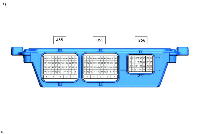
ECM (for 1PP)
*a
Component without harness connected
(ECM)
-
-
Disconnect the cable from the negative (-) battery terminal.
Disconnect the A35 ECM connector.
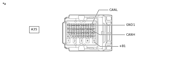
*a
Front view of wire harness connector
(to ECM)
-
-
Measure the resistance according to the value(s) in the table below.
Standard Resistance
Terminal No. (Symbol)
Wiring Color
Terminal Description
Condition
Specified Condition
A35-40 (CANH) - A35-52 (CANL)
B - W
HIGH-level CAN bus line - LOW-level CAN bus line
Cable disconnected from negative (-) battery terminal
108 to 132 Ω
A35-40 (CANH) - A35-53 (GND1)
B - W-B
HIGH-level CAN bus line - Ground
Cable disconnected from negative (-) battery terminal
200 Ω or higher
A35-52 (CANL) - A35-53 (GND1)
W - W-B
LOW-level CAN bus line - Ground
Cable disconnected from negative (-) battery terminal
200 Ω or higher
A35-40 (CANH) - A35-5 (+B1)
B - B
HIGH-level CAN bus line - Battery positive (+)
Cable disconnected from negative (-) battery terminal
6 kΩ or higher
A35-52 (CANL) - A35-5 (+B1)
W - B
LOW-level CAN bus line - Battery positive (+)
Cable disconnected from negative (-) battery terminal
6 kΩ or higher
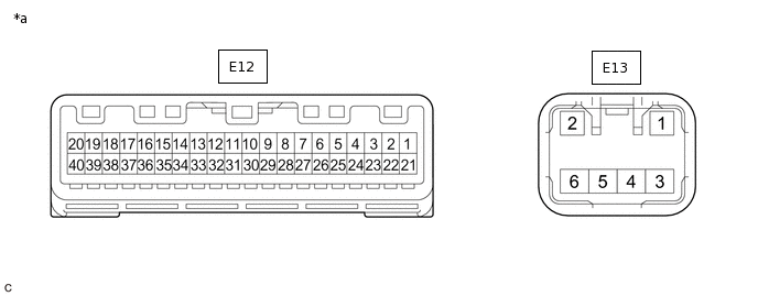
COMBINATION METER ASSEMBLY
*a
Component without harness connected
(Combination Meter Assembly)
-
-
Disconnect the cable from the negative (-) battery terminal.
Disconnect the E12 combination meter assembly connector.
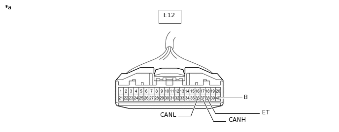
*a
Front view of wire harness connector
(to Combination Meter Assembly)
-
-
Measure the resistance according to the value(s) in the table below.
Standard Resistance
Terminal No. (Symbol)
Wiring Color
Terminal Description
Condition
Specified Condition
E12-37 (CANH) - E12-36 (CANL)
LG - W
HIGH-level CAN bus line - LOW-level CAN bus line
Cable disconnected from negative (-) battery terminal
108 to 132 Ω
E12-37 (CANH) - E12-38 (ET)
LG - W-B
HIGH-level CAN bus line - Ground
Cable disconnected from negative (-) battery terminal
200 Ω or higher
E12-36 (CANL) - E12-38 (ET)
W - W-B
LOW-level CAN bus line - Ground
Cable disconnected from negative (-) battery terminal
200 Ω or higher
E12-37 (CANH) - E12-40 (B)
LG - L
HIGH-level CAN bus line - Battery positive (+)
Cable disconnected from negative (-) battery terminal
6 kΩ or higher
E12-36 (CANL) - E12-40 (B)
W - L
LOW-level CAN bus line - Battery positive (+)
Cable disconnected from negative (-) battery terminal
6 kΩ or higher
SKID CONTROL ECU (BRAKE ACTUATOR ASSEMBLY)
*a
Component without harness connected
(Skid Control ECU (Brake Actuator Assembly))
-
-
Disconnect the cable from the negative (-) battery terminal.
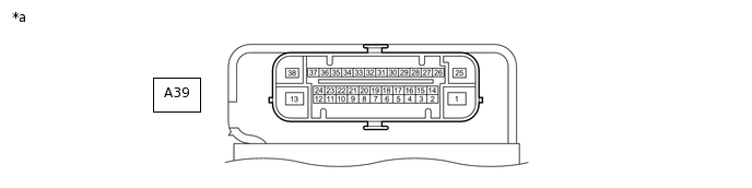
Disconnect the A39 skid control ECU (brake actuator assembly) connector.

*a
Front view of wire harness connector
(to Skid Control ECU (Brake Actuator Assembly))
-
-
Measure the resistance according to the value(s) in the table below.
Standard Resistance
Terminal No. (Symbol)
Wiring Color
Terminal Description
Condition
Specified Condition
A39-26 (CANH) - A39-14 (CANL)
V - W
HIGH-level CAN bus line - LOW-level CAN bus line
Cable disconnected from negative (-) battery terminal
54 to 69 Ω
A39-26 (CANH) - A39-38 (GND1)
V - W-B
HIGH-level CAN bus line - Ground
Cable disconnected from negative (-) battery terminal
200 Ω or higher
A39-14 (CANL) - A39-38 (GND1)
W - W-B
LOW-level CAN bus line - Ground
Cable disconnected from negative (-) battery terminal
200 Ω or higher
A39-26 (CANH) - A39-25 (+BS)
V - R
HIGH-level CAN bus line - Battery positive (+)
Cable disconnected from negative (-) battery terminal
6 kΩ or higher
A39-14 (CANL) - A39-25 (+BS)
W - R
LOW-level CAN bus line - Battery positive (+)
Cable disconnected from negative (-) battery terminal
6 kΩ or higher
STEERING SENSOR (SPIRAL CABLE SUB-ASSEMBLY) (w/ VSC)
*a
Component without harness connected
(Steering Sensor (Spiral Cable Sub-assembly))
-
-
Disconnect the cable from the negative (-) battery terminal.
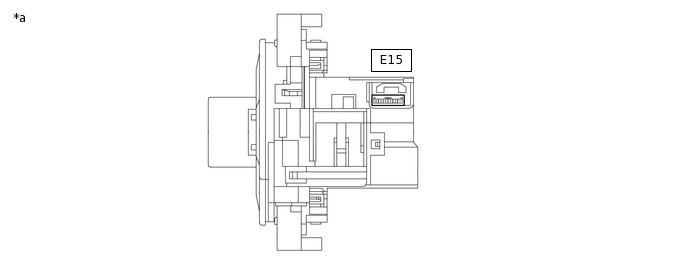
Disconnect the E15 steering sensor (spiral cable sub-assembly) connector.
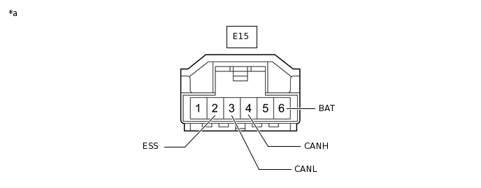
*a
Front view of wire harness connector
(to Steering Sensor (Spiral Cable Sub-assembly))
-
-
Measure the resistance according to the value(s) in the table below.
Standard Resistance
Terminal No. (Symbol)
Wiring Color
Terminal Description
Condition
Specified Condition
E15-4 (CANH) - E15-3 (CANL)
SB - W
HIGH-level CAN bus line - LOW-level CAN bus line
Cable disconnected from negative (-) battery terminal
54 to 69 Ω
E15-4 (CANH) - E15-2 (ESS)
SB - W-B
HIGH-level CAN bus line - Ground
Cable disconnected from negative (-) battery terminal
200 Ω or higher
E15-3 (CANL) - E15-2 (ESS)
W - W-B
LOW-level CAN bus line - Ground
Cable disconnected from negative (-) battery terminal
200 Ω or higher
E15-4 (CANH) - E15-6 (BAT)
SB - GR
HIGH-level CAN bus line - Battery positive (+)
Cable disconnected from negative (-) battery terminal
6 kΩ or higher
E15-3 (CANL) - E15-6 (BAT)
W - GR
LOW-level CAN bus line - Battery positive (+)
Cable disconnected from negative (-) battery terminal
6 kΩ or higher
-
*a
Component without harness connected
(Power Steering ECU Assembly)
-
-
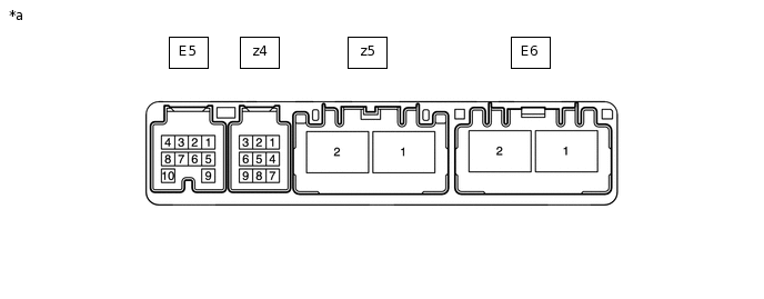
POWER STEERING ECU ASSEMBLY
Disconnect the cable from the negative (-) battery terminal.
Disconnect the E5 and E6 power steering ECU assembly connectors.
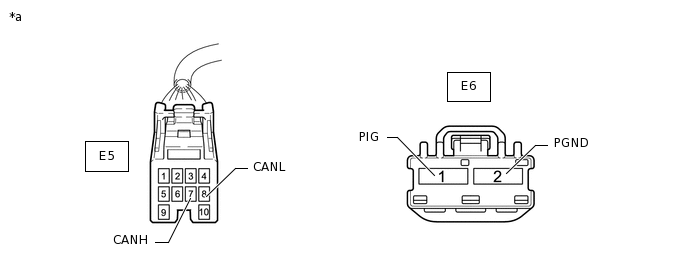
*a
Front view of wire harness connector
(to Power Steering ECU Assembly)
-
-
Measure the resistance according to the value(s) in the table below.
Standard Resistance
Terminal No. (Symbol)
Wiring Color
Terminal Description
Condition
Specified Condition
E5-7 (CANH) - E5-8 (CANL)
GR - W
HIGH-level CAN bus line - LOW-level CAN bus line
Cable disconnected from negative (-) battery terminal
54 to 69 Ω
E5-7 (CANH) - E6-2 (PGND)
GR - W-B
HIGH-level CAN bus line - Ground
Cable disconnected from negative (-) battery terminal
200 Ω or higher
E5-8 (CANL) - E6-2 (PGND)
W - W-B
LOW-level CAN bus line - Ground
Cable disconnected from negative (-) battery terminal
200 Ω or higher
E5-7 (CANH) - E6-1 (PIG)
GR - B
HIGH-level CAN bus line - Battery positive (+)
Cable disconnected from negative (-) battery terminal
6 kΩ or higher
E5-8 (CANL) - E6-1 (PIG)
W - B
LOW-level CAN bus line - Battery positive (+)
Cable disconnected from negative (-) battery terminal
6 kΩ or higher
AIRBAG SENSOR ASSEMBLY
*a
Component without harness connected
(Airbag Sensor Assembly)
-
-
Disconnect the cable from the negative (-) battery terminal.
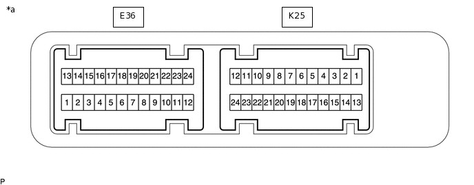
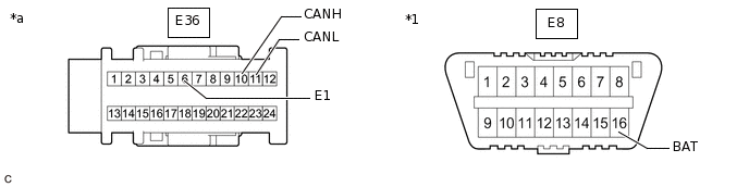
Disconnect the E36 airbag sensor assembly connector.
*1
DLC3
-
-
*a
Front view of wire harness connector
(to Airbag Sensor Assembly)
-
-
Measure the resistance according to the value(s) in the table below.
Standard Resistance
Terminal No. (Symbol)
Wiring Color
Terminal Description
Condition
Specified Condition
E36-10 (CANH) - E36-11 (CANL)
V - W
HIGH-level CAN bus line - LOW-level CAN bus line
Cable disconnected from negative (-) battery terminal
54 to 69 Ω
E36-10 (CANH) - E36-6 (E1)
V - W-B
HIGH-level CAN bus line - Ground
Cable disconnected from negative (-) battery terminal
200 Ω or higher
E36-11 (CANL) - E36-6 (E1)
W - W-B
LOW-level CAN bus line - Ground
Cable disconnected from negative (-) battery terminal
200 Ω or higher
E36-10 (CANH) - E8-16 (BAT)
V - GR
HIGH-level CAN bus line - Battery positive (+)
Cable disconnected from negative (-) battery terminal
6 kΩ or higher
E36-11 (CANL) - E8-16 (BAT)
W - GR
LOW-level CAN bus line - Battery positive (+)
Cable disconnected from negative (-) battery terminal
6 kΩ or higher
CERTIFICATION ECU (SMART KEY ECU ASSEMBLY) (w/ Entry and Start System)
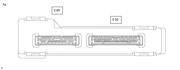
*a
Component without harness connected
(Certification ECU (Smart Key ECU Assembly))
-
-
Disconnect the cable from the negative (-) battery terminal.
Disconnect the E49 and E50 certification ECU (smart key ECU assembly) connectors.
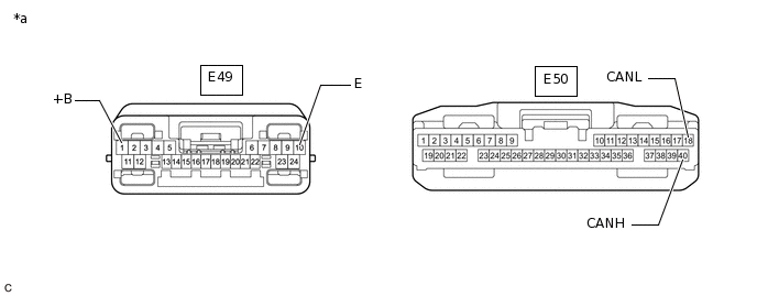
*a
Front view of wire harness connector
(to Certification ECU (Smart Key ECU Assembly))
-
-
Measure the resistance according to the value(s) in the table below.
Standard Resistance
Terminal No. (Symbol)
Wiring Color
Terminal Description
Condition
Specified Condition
E50-40 (CANH) - E50-18 (CANL)
R - W
HIGH-level CAN bus line - LOW-level CAN bus line
Cable disconnected from negative (-) battery terminal
54 to 69 Ω
E50-40 (CANH) - E49-10 (E)
R- BR
HIGH-level CAN bus line - Ground
Cable disconnected from negative (-) battery terminal
200 Ω or higher
E50-18 (CANL) - E49-10 (E)
W - BR
LOW-level CAN bus line - Ground
Cable disconnected from negative (-) battery terminal
200 Ω or higher
E50-40 (CANH) - E49-1 (+B)
R - B
HIGH-level CAN bus line - Battery positive (+)
Cable disconnected from negative (-) battery terminal
6 kΩ or higher
E50-18 (CANL) - E49-1 (+B)
W - B
LOW-level CAN bus line - Battery positive (+)
Cable disconnected from negative (-) battery terminal
6 kΩ or higher
RADIO AND DISPLAY RECEIVER ASSEMBLY (for Radio and Display Type)
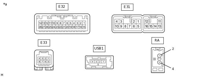
*a
Component without harness connected
(Radio and Display Receiver Assembly)
-
-
Disconnect the cable from the negative (-) battery terminal.
Disconnect the E31 and E32 radio and display receiver assembly connectors.
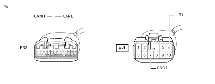
*a
Front view of wire harness connector
(to Radio and Display Receiver Assembly)
-
-
Measure the resistance according to the value(s) in the table below.
Standard Resistance
Terminal No. (Symbol)
Wiring Color
Terminal Description
Condition
Specified Condition
E32-6 (CANH) - E32-7 (CANL)
G - W
HIGH-level CAN bus line - LOW-level CAN bus line
Cable disconnected from negative (-) battery terminal
54 to 69 Ω
E32-6 (CANH) - E31-7 (GND1)
G - BR
HIGH-level CAN bus line - Ground
Cable disconnected from negative (-) battery terminal
200 Ω or higher
E32-7 (CANL) - E31-7 (GND1)
W - BR
LOW-level CAN bus line - Ground
Cable disconnected from negative (-) battery terminal
200 Ω or higher
E32-6 (CANH) - E31-4 (+B1)
G - SB
HIGH-level CAN bus line - Battery positive (+)
Cable disconnected from negative (-) battery terminal
6 kΩ or higher
E32-7 (CANL) - E31-4 (+B1)
W - SB
LOW-level CAN bus line - Battery positive (+)
Cable disconnected from negative (-) battery terminal
6 kΩ or higher
-
*a
Component without harness connected
(Air Conditioning Control Assembly)
-
-
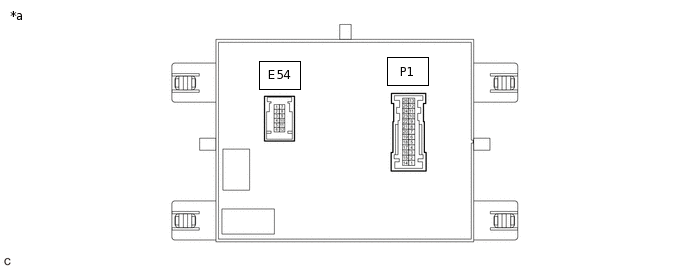
AIR CONDITIONING CONTROL ASSEMBLY (for Automatic Air Conditioning System)
Disconnect the cable from the negative (-) battery terminal.
Disconnect the E54 air conditioning control assembly connector.
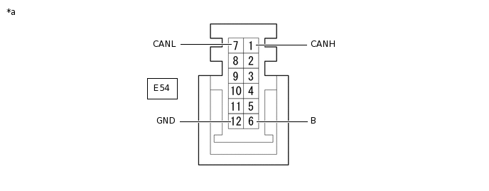
*a
Front view of wire harness connector
(to Air Conditioning Control Assembly)
-
-
Measure the resistance according to the value(s) in the table below.
Standard Resistance
Terminal No. (Symbol)
Wiring Color
Terminal Description
Condition
Specified Condition
E54-1 (CANH) - E54-7 (CANL)
Y - W
HIGH-level CAN bus line - LOW-level CAN bus line
Cable disconnected from negative (-) battery terminal
54 to 69 Ω
E54-1 (CANH) - E54-12 (GND)
Y - W-B
HIGH-level CAN bus line - Ground
Cable disconnected from negative (-) battery terminal
200 Ω or higher
E54-7 (CANL) - E54-12 (GND)
W - W-B
LOW-level CAN bus line - Ground
Cable disconnected from negative (-) battery terminal
200 Ω or higher
E54-1 (CANH) - E54-6 (B)
Y - P*1
Y - SB*2
HIGH-level CAN bus line - Battery positive (+)
Cable disconnected from negative (-) battery terminal
6 kΩ or higher
E54-7 (CANL) - E54-6 (B)
W - P*1
W - SB*2
LOW-level CAN bus line - Battery positive (+)
Cable disconnected from negative (-) battery terminal
6 kΩ or higher
*1: w/o Stop and Start System
*2: w/ Stop and Start System
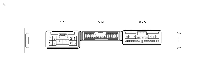
ENGINE STOP AND START ECU (w/ Stop and Start System)
*a
Component without harness connected
(Engine Stop and Start ECU)
-
-
Disconnect the cable from the negative (-) battery terminal.
Disconnect the A23 and A25 engine stop and start ECU connectors.
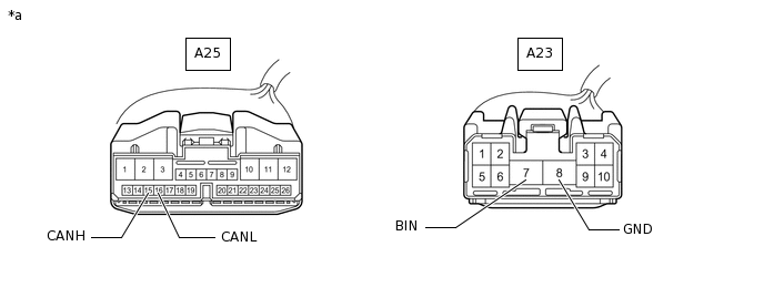
*a
Front view of wire harness connector
(to Engine Stop and Start ECU)
-
-
Measure the resistance according to the value(s) in the table below.
Standard Resistance
Terminal No. (Symbol)
Wiring Color
Terminal Description
Condition
Specified Condition
A25-15 (CANH) - A25-16 (CANL)
P - W
HIGH-level CAN bus line - LOW-level CAN bus line
Cable disconnected from negative (-) battery terminal
54 to 69 Ω
A25-15 (CANH) - A23-8 (GND)
P - W-B
HIGH-level CAN bus line - Ground
Cable disconnected from negative (-) battery terminal
200 Ω or higher
A25-16 (CANL) - A23-8 (GND)
W - W-B
LOW-level CAN bus line - Ground
Cable disconnected from negative (-) battery terminal
200 Ω or higher
A25-15 (CANH) - A23-7 (BIN)
P - L
HIGH-level CAN bus line - Battery positive (+)
Cable disconnected from negative (-) battery terminal
6 kΩ or higher
A25-16 (CANL) - A23-7 (BIN)
W - L
LOW-level CAN bus line - Battery positive (+)
Cable disconnected from negative (-) battery terminal
6 kΩ or higher
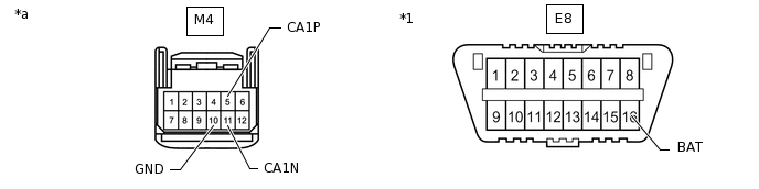
PRE-CRASH SAFETY CITY SENSOR (w/ Toyota Safety Sense)

*a
Component without harness connected
(Pre-crash Safety City Sensor)
-
-
Disconnect the cable from the negative (-) battery terminal.
Disconnect the M4 pre-crash safety city sensor connector.
Measure the resistance according to the value(s) in the table below.
*1
DLC3
-
-
*a
Front view of wire harness connector
(to Pre-crash Safety City Sensor)
-
-
Standard Resistance
Terminal No. (Symbol)
Wiring Color
Terminal Description
Condition
Specified Condition
M4-5 (CA1P) - M4-11 (CA1N)
B - W
HIGH-level CAN bus line - LOW-level CAN bus line
Cable disconnected from negative (-) battery terminal
54 to 69 Ω
M4-5 (CA1P) - M4-10 (GND)
B - W-B
HIGH-level CAN bus line - Ground
Cable disconnected from negative (-) battery terminal
200 Ω or higher
M4-11 (CA1N) - M4-10 (GND)
W - W-B
LOW-level CAN bus line - Ground
Cable disconnected from negative (-) battery terminal
200 Ω or higher
M4-5 (CA1P) - E8-16 (BAT)
B - GR
HIGH-level CAN bus line - Battery positive (+)
Cable disconnected from negative (-) battery terminal
6 kΩ or higher
M4-11 (CA1N) - E8-16 (BAT)
W - GR
LOW-level CAN bus line - Battery positive (+)
Cable disconnected from negative (-) battery terminal
6 kΩ or higher