SFI SYSTEM
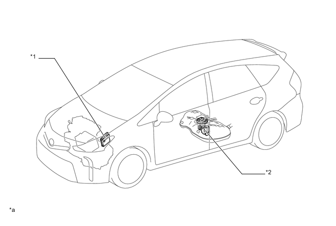
| *1 | ECM | *2 | Fuel Suction Tube with Pump and Gauge Assembly |
| *a | The illustration shown is an example only. | - | - |
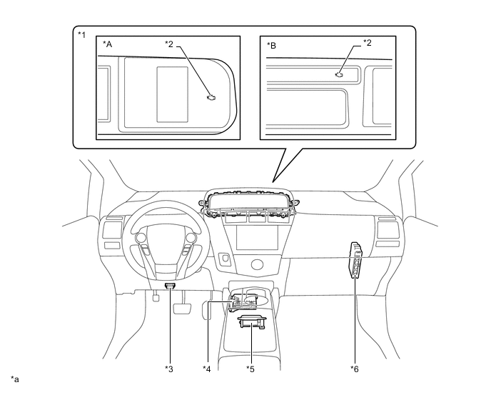
| *A | Models with Multi-information Display | *B | Models without Multi-information Display |
| *1 | Combination Meter Sub-assembly | *2 | Malfunction Indicator Lamp |
| *3 | DLC3 | *4 | Air Conditioning Amplifier Assembly |
| *5 | Airbag ECU Assembly | *6 | Power Management Control ECU |
| *a | The illustration shown is an example only. | - | - |
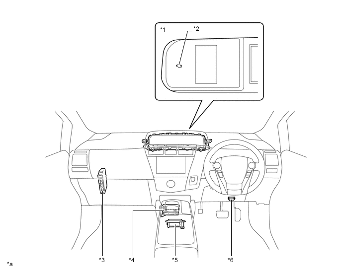
| *1 | Combination Meter Sub-assembly | *2 | Malfunction Indicator Lamp |
| *3 | Power Management Control ECU | *4 | Air Conditioning Amplifier Assembly |
| *5 | Airbag ECU Assembly | *6 | DLC3 |
| *a | The illustration shown is an example only. | - | - |
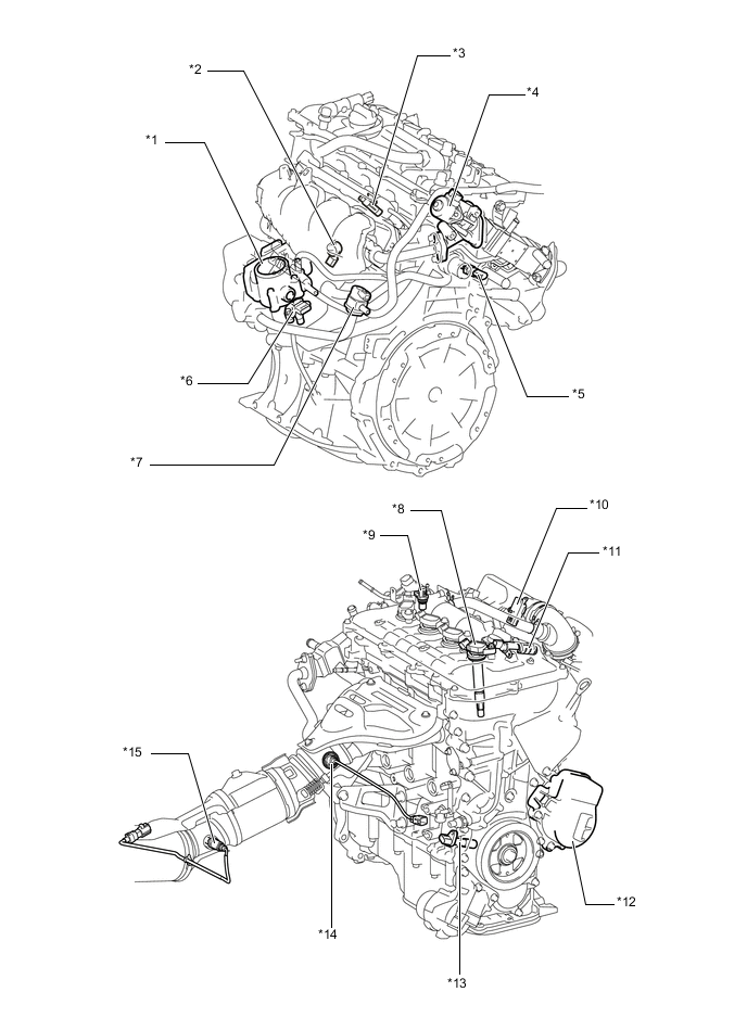
| *1 | Throttle Body Assembly - Throttle Control Motor - Throttle Position Sensor |
*2 | Knock Control Sensor |
| *3 | Fuel Injector Assembly | *4 | EGR Valve Assembly |
| *5 | E. F. I. Engine Coolant Temperature Sensor | *6 | E. F. I. Vacuum Sensor Assembly |
| *7 | Purge VSV | *8 | Ignition Coil Assembly |
| *9 | Cam Position Sensor (No. 1 Crank Position Sensor) | *10 | Intake Mass Air Flow Meter Sub-assembly - Intake Air Temperature Sensor |
| *11 | Camshaft Timing Oil Control Valve Assembly | *12 | Engine Water Pump Assembly |
| *13 | Crank Position Sensor | *14 | Air Fuel Ratio Sensor (Bank 1, Sensor 1) |
| *15 | Oxygen Sensor (Bank 1, Sensor 2) | - | - |