ECD SYSTEM (for DPF), Diagnostic DTC:P0088
| DTC Code | DTC Name |
|---|---|
| P0088 | Fuel Rail / System Pressure - Too High |
DESCRIPTION
| DTC Detection Drive Pattern | DTC Detection Condition | Trouble Area |
|---|---|---|
| After idling for 60 seconds, quickly increase engine speed to 2500 rpm repeatedly for 30 seconds | The fuel pressure of the common rail exceeds 220000 kPa (2243 kgf/cm2, 31900 psi) (1 trip detection logic). |
|
| DTC No. | Data List |
|---|---|
| P0088 |
|
Tech Tips
-
For more information on the fuel supply pump assembly (suction control valve) and common rail system, refer to System Description Click here.
-
When DTC P0088 is stored, check the internal fuel pressure of the common rail by entering the following menus: Powertrain / Engine and ECT / Data List / Fuel Press.
Reference Engine Speed Fuel Press Idling Approximately 30000 to 50000 kPa 3000 rpm (No engine load) Approximately 60000 to 95000 kPa -
Check "Fuel Press", "Target Common Rail Pressure" and "Target Pump SCV Current" in the freeze frame data.
MONITOR DESCRIPTION
P0088 (Internal fuel pressure too high):The ECM stores this DTC if the fuel pressure inside the common rail is higher than 220000 kPa (2243 kgf/cm2, 31900 psi). This DTC indicates that: 1) the suction control valve may be stuck open, or 2) there may be a short in the suction control valve circuit.
If this DTC is stored, the ECM enters fail-safe mode and limits the engine power. The ECM continues operating in fail-safe mode until the ignition switch is turned off.
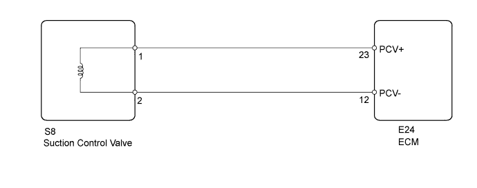
WIRING DIAGRAM
INSPECTION PROCEDURE
Note
-
Inspect the fuses of circuits related to this system before performing the following inspection procedure.
-
After replacing the ECM, the new ECM needs registration Click here and initialization Click here.
-
After replacing the fuel supply pump assembly, the ECM needs initialization Click here.
-
After replacing an injector assembly, the ECM needs registration Click here.
Tech Tips
Read freeze frame data using the intelligent tester. Freeze frame data records the engine condition when malfunctions are detected. When troubleshooting, freeze frame data can help determine if the vehicle was moving or stationary, if the engine was warmed up or not, and other data from the time the malfunction occurred.
PROCEDURE
-
CHECK FOR ANY OTHER DTCS OUTPUT (IN ADDITION TO DTC P0088)
-
Connect the intelligent tester to the DLC3.
-
Turn the ignition switch to ON and turn the tester on.
-
Enter the following menus: Powertrain / Engine and ECT / DTC.
-
Read Current DTCs.
Result Result Proceed to P0088 is output A P0088 and "P0190, P0192 and/or P0193" are output B Tech Tips
When there is an open circuit in the fuel pressure sensor circuit, the fuel pressure sensor outputs the maximum value. Therefore, P0088 may be stored together with DTCs which indicate common rail fuel pressure sensor circuit malfunctions.
B 
GO TO FUEL RAIL PRESSURE SENSOR CIRCUIT Click here
A 
-
-
CHECK FREEZE FRAME DATA (FUEL PRESS)
-
Connect the intelligent tester to the DLC3.
-
Turn the ignition switch to ON and turn the tester on.
-
Enter the following menus: Powertrain / Engine and ECT / DTC.
-
Record the stored DTCs and freeze frame data.
Result Result Proceed to Value of Fuel Press is shifting towards 160000 kPa or higher in 3rd and 4th set of freeze frame data B Except above A
B 
REPLACE FUEL SUPPLY PUMP ASSEMBLY (SUCTION CONTROL VALVE) Click here
A
-
-
INSPECT ECM (FUEL PRESSURE SENSOR OUTPUT VOLTAGE)
-
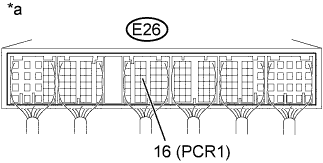
Text in Illustration *a Component with harness connected
(ECM)
Connect the positive (+) probe of an oscilloscope to the fuel pressure sensor input terminal of the ECM connector and the negative (-) probe to the body ground.
-
Turn the ignition switch to ON.
-
Check for any noise in the waveform when vibration is applied to the wire harness and connectors between the fuel pressure sensor and ECM.
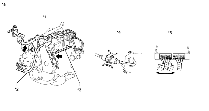
Text in Illustration *1 Engine *2 Engine Wire *3 Common Rail Assembly (Fuel Pressure Sensor) 4 Wire to Wire *5 ECM - - *a Vibration Method (Reference) - - 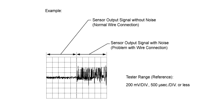
Standard Voltage Tester Connection Condition Specified Condition E26-16 (PCR1) - Body ground Vibration is applied to the wire harness and connectors No noise in the waveform Result Result Proceed to MIL comes on or noise present in the waveform B Except above A
B
REPAIR OR REPLACE HARNESS OR CONNECTOR Click here
A
-
-
REPLACE FUEL SUPPLY PUMP ASSEMBLY (SUCTION CONTROL VALVE)
-
Replace the fuel supply pump assembly Click here.
Tech Tips
Before replacing the fuel supply pump assembly, check that the wire harness between the suction control valve and ECM is not shorted to ground.
When there is a malfunction in the wire harness, Target Pump SCV Current is outside the range of 923 to 1123 mA when idling, and outside the range of 1013 to 1212 mA when the engine is running at 2500 rpm without load.
If there are no problems with the engine condition during idling, it is not necessary to perform the above wire harness inspection.
When the wire harness between the suction control valve and ECM is not shorted to ground, it can be assumed that DTC P0088 was stored due to a malfunction in the operation of the suction control valve. Therefore, it is necessary to replace the fuel supply pump assembly.
NEXT
-
-
BLEED AIR FROM FUEL SYSTEM
-
Bleed the air from the fuel system Click here.
NEXT
-
-
PERFORM FUEL SUPPLY PUMP INITIALIZATION
-
Perform fuel supply pump initialization Click here.
NEXT
-
-
CHECK DTC OUTPUT
-
Connect the intelligent tester to the DLC3.
-
Clear the DTCs Click here.
-
Turn the ignition switch off for 30 seconds or more.
-
Turn the ignition switch to ON and start the engine.
-
After idling for 60 seconds, increase the engine speed from idling to 2500 rpm repeatedly for 30 seconds.
-
Confirm that the DTC is not output again.
Tech Tips
Perform the following procedure using the tester to determine whether or not the DTC judgment has been carried out.
-
Enter the following menus: Powertrain / Engine and ECT / Utility / All Readiness.
-
Input DTC P0088.
-
Check the DTC judgment result.
Result Tester Display Result Proceed to Pending DTC P0088 is output A All Readiness NORMAL B ABNORMAL A Tech Tips
If STATUS is INCOMPLETE or N/A, race the engine to 2500 rpm repeatedly for 30 seconds and increase the idling time.
-
B
END
A
-
-
REPLACE ECM
-
Replace the ECM Click here.
NEXT
CONFIRM WHETHER MALFUNCTION HAS BEEN SUCCESSFULLY REPAIRED Click here
-
-
REPAIR OR REPLACE HARNESS OR CONNECTOR
-
Repair or replace the harness or connector.
NEXT
-
-
INSPECT ECM (FUEL PRESSURE SENSOR OUTPUT VOLTAGE)
-
Text in Illustration *a Component with harness connected
(ECM)
Connect the positive (+) probe of an oscilloscope to the fuel pressure sensor input terminal of the ECM connector and the negative (-) probe to the body ground.
-
Turn the ignition switch to ON.
-
Check for any noise in the waveform when vibration is applied to the wire harness and connectors between the fuel pressure sensor and ECM.
Standard Voltage Tester Connection Condition Specified Condition E26-16 (PCR1) - Body ground Vibration is applied to the wire harness and connectors No noise in the waveform Result Result Proceed to MIL comes on or noise present in the waveform A Except above B
B
CONFIRM WHETHER MALFUNCTION HAS BEEN SUCCESSFULLY REPAIRED Click here
A
-
-
REPLACE COMMON RAIL ASSEMBLY
-
Replace the common rail assembly Click here.
NEXT
-
-
BLEED AIR FROM FUEL SYSTEM
-
Bleed the air from the fuel system Click here.
NEXT
-
-
CONFIRM WHETHER MALFUNCTION HAS BEEN SUCCESSFULLY REPAIRED
-
Connect the intelligent tester to the DLC3.
-
Clear the DTCs Click here.
-
Turn the ignition switch off for 30 seconds or more.
-
Turn the ignition switch to ON and start the engine.
-
After idling for 60 seconds, increase the engine speed from idling to 2500 rpm repeatedly for 30 seconds.
-
Confirm that the DTC is not output again.
Tech Tips
Perform the following procedure using the tester to determine whether or not the DTC judgment has been carried out.
-
Enter the following menus: Powertrain / Engine and ECT / Utility / All Readiness.
-
Input DTC P0088.
-
Check that STATUS is NORMAL. If STATUS is INCOMPLETE or N/A, race the engine to 2500 rpm repeatedly for 30 seconds and increase the idling time.
-
NEXT 
END
-