G-BOOK SYSTEM(w/ Telematics Transceiver) "NCON" is Displayed in "DCM" on the System Check Mode Screen
| DTC Code | DTC Name |
|---|---|
| "NCON" is Displayed in "DCM" on the System Check Mode Screen |
DESCRIPTION
If the display and navigation module display cannot detect the DCM for a certain period of time (15 seconds) after the engine switch is turned on (ACC) and the display and navigation module display confirms that the information is missing by checking past DCM recognition information (registered information), "NCON" will be displayed.
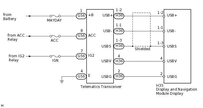
The G-BOOK system uses USB communication between devices. If an open, short, short to +B or short to ground occurs in the USB circuit, communication is interrupted and the G-BOOK system will not operate normally.
WIRING DIAGRAM
CAUTION / NOTICE / HINT
Inspect the fuse for circuits related to this system before performing the following inspection procedure.
When replacing the display and navigation module display or the telematics transceiver, perform the vehicle contract setting (Click here).
PROCEDURE
CHECK HARNESS AND CONNECTOR (TELEMATICS TRANSCEIVER - BATTERY AND BODY GROUND)
-
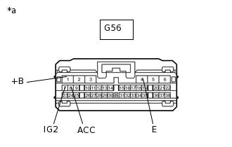
*a
Front view of wire harness connector
(to Telematics Transceiver)
Disconnect the G56 telematics transceiver connector.
Measure the resistance according to the value(s) in the table below.
Standard Resistance
Tester Connection
Condition
Specified Condition
G56-4 (E) - Body ground
Always
Below 1 Ω
Measure the voltage according to the value(s) in the table below.
Standard Voltage
Tester Connection
Switch Condition
Specified Condition
G56-1 (+B) - Body ground
Engine switch off
11 to 14 V
G56-7 (IG2) - Body ground
Engine switch on (IG)
11 to 14 V
G56-8 (ACC) - Body ground
Engine switch on (ACC)
11 to 14 V
Result
Result
OK
NG
NG REPAIR OR REPLACE HARNESS OR CONNECTOR
-
INSPECT DISPLAY AND NAVIGATION MODULE DISPLAY (USBV, USBG)
-
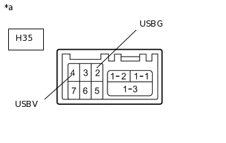
*a
Component without harness connected
(Display and Navigation Module Display)
Disconnect the H35 display and navigation module display connector.
Measure the resistance according to the value(s) in the table below.
Standard Resistance
Tester Connection
Condition
Specified Condition
H35-2 (USBG) - Body ground
Always
Below 1 Ω
Measure the voltage according to the value(s) in the table below.
Standard Voltage
Tester Connection
Switch Condition
Specified Condition
H35-4 (USBV) - H35-2 (USBG)
Engine switch on (ACC)
5 V
Result
Result
OK
NG
-
CHECK HARNESS AND CONNECTOR (DISPLAY AND NAVIGATION MODULE DISPLAY - TELEMATICS TRANSCEIVER)
Check the installation condition.
Check the USB communication cable (digital communication cable) between the display and navigation module display and the telematics transceiver for any installation or connection problems.
Disconnect the H35 display and navigation module display connector.
Disconnect the H36 telematics transceiver connector.
Measure the resistance according to the value(s) in the table below.
Standard Resistance
Tester Connection
Condition
Specified Condition
H35-4 (USBV) - H36-4 (USBV)
Always
Below 1 Ω
H35-2 (USBG) - H36-2 (USBG)
Always
Below 1 Ω
H35-1-2 (USB+) - H36-1-2 (USB+)
Always
Below 1 Ω
H35-1-1 (USB-) - H36-1-1 (USB-)
Always
Below 1 Ω
H35-1-3 (USBS) - H36-1-3 (USBS)
Always
Below 1 Ω
H35-4 (USBV) - Body ground
Always
10 kΩ or higher
H35-2 (USBG) - Body ground
Always
10 kΩ or higher
H35-1-2 (USB+) - Body ground
Always
10 kΩ or higher
H35-1-1 (USB-) - Body ground
Always
10 kΩ or higher
H35-1-3 (USBS) - Body ground
Always
10 kΩ or higher
Result
Result
OK
NG
NG REPAIR OR REPLACE HARNESS OR CONNECTOR
REPLACE TELEMATICS TRANSCEIVER
Replace the telematics transceiver with a normal one.
Perform inspections indicated on the System Check Mode screen to confirm the DCM inspection result.
Result
Result
Proceed to
"OK" displayed for "DCM" on System Check Mode screen
A
"NCON" displayed for "DCM" on System Check Mode screen
B
A END