ENGINE UNIT REPAIR
-
REPAIR INTAKE VALVE SEAT
-

Apply a light coat of Prussian blue (or white lead) to the valve face.
-
Lightly press the valve face against the valve seat.
-
Check the valve face and valve seat according to the following procedures.
-
If blue appears 360° around the valve face, the valve face is concentric. If not, replace the valve.
-
If blue appears 360° around the valve seat, the guide and valve face are concentric. If not, resurface the valve seat.
-
Check that the valve seat contact is in the middle of the valve face with the width between 1.0 to 1.4 mm (0.039 to 0.055 in.).
Note
Keep the lip free from foreign matter.
-
-
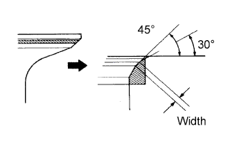
If the seating is too high on the valve face, use 30° and 45° cutters to correct the seat.
-
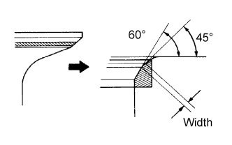
If the seating is too low on the valve face, use 60° and 45° cutters to correct the seat.
-
Hand-lap the valve and valve seat with an abrasive compound.
-
Check the valve seating position.
-
-
REPAIR EXHAUST VALVE SEAT
-

Apply a light coat of Prussian blue (or white lead) to the valve face.
-
Lightly press the valve face against the valve seat.
-
Check the valve face and valve seat according to the following procedures.
-
If blue appears 360° around the valve face, the valve face is concentric. If not, replace the valve.
-
If blue appears 360° around the valve seat, the guide and valve face are concentric. If not, resurface the valve seat.
-
Check that the valve seat contact is in the middle of the valve face with the width between 1.0 to 1.4 mm (0.039 to 0.055 in.).
Note
Keep the lip free from foreign matter.
-
-
If the seating is too high on the valve face, use 30° and 45° cutters to correct the seat.
-
If the seating is too low on the valve face, use 60° and 45° cutters to correct the seat.
-
Hand-lap the valve and valve seat with an abrasive compound.
-
Check the valve seating position.
-
-
BORE CYLINDER
Tech Tips
-
Bore all the 4 cylinders for the O/S piston outside diameter.
-
Replace all the piston rings with ones to match the O/S pistons.
-
Keep 4 new O/S pistons.
O/S 0.50 piston diameter 86.456 to 86.486 mm (3.4038 to 3.4050 in.) -
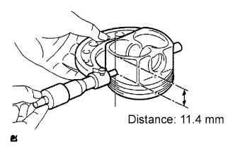
Using a micrometer, measure the piston diameter at right angles to the piston center line, the indicated distance from the piston end.
Standard distance 11.4 mm (0.449 in.) -
Calculate how much each cylinder needs to be rebored:
Size to be rebored = P + C - H P = Piston diameter C = Piston clearance: 0.040 to 0.047 mm (0.0016 to 0.0019 in.) H = Allowance for honing: 0.02 mm (0.0008 in.) or less -
Bore and hone the cylinders to calculated dimensions.
Maximum honing 0.02 mm (0.0008 in.) Note
Excess honing will destroy the finished roundness.
-