REAR SEAT ENTERTAINMENT SYSTEM TERMINALS OF ECU
CHECK MULTI-DISPLAY CONTROLLER SUB-ASSEMBLY
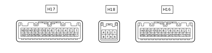 Tip:
Tip:Perform the check from the rear of the connector while it is connected to the multi-display controller sub-assembly.
Terminal No. (Symbol)
Wiring Color
Terminal Description
Condition
Specified Condition
H16-1 (MI+)
B
MOST communication signal
-
-
H16-2 (MI-)
W
MOST communication signal
-
-
H16-3 (SLDI) - Body ground
BR - Body ground
Shield ground
Always
Below 1 V
H16-4 (SLDO) - Body ground
BR - Body ground
Shield ground
Always
Below 1 V
H16-5 (MO-)
W
MOST communication signal
-
-
H16-6 (MO+)
B
MOST communication signal
-
-
H16-7 (WUI) - H16-21 (GND)
L - BR
MOST communication wake up signal
Engine switch on (ACC)
4.5 V or higher
Engine switch off
Below 1 V
H16-9 (GND1) - H16-21 (GND)
P - BR
Ground
Always
Below 1 V
H16-10 (GND2) - H16-21 (GND)
GR - BR
Ground
Always
Below 1 V
H16-11 (VMTR) - H16-21 (GND)
W - BR
Visual mute signal
RSE playing → Source changed
Higher than 3.5 V → Below 1 V
H16-12 (PWR1) - H16-21 (GND)
V - BR
Power supply for television display assembly RH
Engine switch on (IG)
11 to 14 V
H16-13 (PWR2) - H16-21 (GND)
P - BR
Power supply for television display assembly LH
Engine switch on (IG)
11 to 14 V
H16-14 (+B) - H16-21 (GND)
SB - BR
Battery
Always
11 to 14 V
H16-15 (NTS4) - H16-21 (GND)
G - BR
DVD image signal
DVD playing
Waveform synchronized with display signal is output
H16-16 (SGN4) - Body ground
R - Body ground
DVD image signal ground
Always
Below 1 V
H16-21 (GND) - Body ground
BR - Body ground
Ground
Always
Below 1 V
H16-22 (GND5) - Body ground
BR - Body ground
Ground
Always
Below 1 V
H16-23 (GND3) - Body ground
L - Body ground
Ground
Always
Below 1 V
H16-24 (GND4) - Body ground
L - Body ground
Ground
Always
Below 1 V
H16-25 (MDO) - H16-21 (GND)
GR - BR
LH/RH display recognition signal
Always
Below 1 V
H16-28 (+B1) - H16-21 (GND)
SB - BR
Battery
Always
11 to 14 V
H17-1 (NTS2) - H16-21 (GND)
W - BR
Display signal
RSE playing
Waveform synchronized with display signal is output
H17-2 (SGN2) - Body ground
B - Body ground
Display signal ground
Always
Below 1 V
H17-3 (SLDB) - Body ground
Shielded - Body ground
Shield ground
Always
Below 1 V
H17-4 (VMT2) - H16-21 (GND)
SB - BR
Visual mute signal
Display operating → Source changed
Higher than 3.5 V → Below 1 V
H17-5 (TX2+)
L
AVC-LAN communication signal
-
-
H17-6 (TX2-)
LG
AVC-LAN communication signal
-
-
H17-7 (MUT1) - H16-21 (GND)
LG - BR
Mute signal
RSE playing → Source changed
Higher than 3.5 V → Below 1 V
H17-8 (MUT2) - H16-21 (GND)
LG - BR
Mute signal
RSE playing → Source changed
Higher than 3.5 V → Below 1 V
H17-9 (HP1R) - H16-21 (GND)
W - BR
RSE sound signal
RSE playing
Waveform synchronized with sound is output
H17-10 (SG1) - H16-21 (GND)
Shielded - BR
Shield ground
Always
Below 1 V
H17-11 (HP1L) - H16-21 (GND)
B - BR
RSE sound signal
RSE playing
Waveform synchronized with sound is output
H17-13 (HP2R) - H16-21 (GND)
Y - BR
RSE sound signal
RSE playing
Waveform synchronized with sound is output
H17-14 (SG2) - H16-21 (GND)
Shielded - BR
Shield ground
Always
Below 1 V
H17-15 (HP2L) - H16-21 (GND)
BR - BR
RSE sound signal
RSE playing
Waveform synchronized with sound is output
H17-17 (NTS1) - H16-21 (GND)
W - BR
Display signal
RSE playing
Waveform synchronized with display signal is output
H17-18 (SGN1) - H16-21 (GND)
B - BR
Display signal ground
Always
Below 1 V
H17-19 (SLDA) - Body ground
Shielded - Body ground
Shield ground
Always
Below 1 V
H17-20 (VMT1) - H16-21 (GND)
SB -BR
Visual mute signal
Display operating → Source changed
Higher than 3.5 V → Below 1 V
H17-21 (TX1+)
L
AVC-LAN communication signal
-
-
H17-22 (TX1-)
LG
AVC-LAN communication signal
-
-
H17-23 (SLD1) - Body ground
Shielded - Body ground
Shield ground
Always
Below 1 V
H17-24 (R1+) - H16-21 (GND)
B - BR
Sound signal
RSE playing
Waveform synchronized with sound signal is output
H17-25 (R1-) - H16-21 (GND)
W - BR
Sound signal
RSE playing
Waveform synchronized with sound signal is output
H17-26 (L1+) - H16-21 (GND)
R - BR
Sound signal
RSE playing
Waveform synchronized with sound signal is output
H17-27 (L1-) - H16-21 (GND)
G - BR
Sound signal
RSE playing
Waveform synchronized with sound signal is output
H17-28 (SLD2) - Body ground
Shielded - Body ground
Shield ground
Always
Below 1 V
H17-29 (R2+) - H16-21 (GND)
B - BR
Sound signal
RSE playing
Waveform synchronized with sound signal is output
H17-30 (R2-) - H16-21 (GND)
W - BR
Sound signal
RSE playing
Waveform synchronized with sound signal is output
H17-31 (L2+) - H16-21 (GND)
R - BR
Sound signal
RSE playing
Waveform synchronized with sound signal is output
H17-32 (L2-) - H16-21 (GND)
G - BR
Sound signal
RSE playing
Waveform synchronized with sound signal is output
H18-1 (R+) - H16-21 (GND)
W - BR
Sound signal
External device playing (when video terminal used)
Waveform synchronized with sound signal is output
H18-2 (L+) - H16-21 (GND)
B - BR
Sound signal
External device playing (when video terminal used)
Waveform synchronized with sound signal is output
H18-3 (SGN3) - H16-21 (GND)
R - BR
Sound signal ground
Always
Below 1 V
H18-4 (SGN6) - Body ground
Shielded - Body ground
Video terminal detection ground
Always
Below 1 V
H18-5 (VD) - H16-21 (GND)
G - BR
Video signal
External device playing (when video terminal used)
Waveform synchronized with sound signal is output
H18-6 (VG) - Body ground
R - Body ground
Video signal ground
Always
Below 1 V
H18-7 (SGN5) - Body ground
Shielded - Body ground
Shield ground
Always
Below 1 V
H18-8 (ADPI) - H16-21 (GND)
L - BR
Video terminal connection detection signal
External device connected
Below 1 V
CHECK TELEVISION DISPLAY ASSEMBLY LH
 Tip:
Tip:Perform the check from the rear of the connector while it is connected to the television display assembly LH.
Terminal No. (Symbol)
Wiring Color
Terminal Description
Condition
Specified Condition
g2-1 - g2-20
BR - V
Sound signal
RSE playing
Waveform synchronized with sound signal is output
g2-2 - g2-20
SB - V
Sound signal
RSE playing
Waveform synchronized with sound signal is output
g2-3 - g2-20
LG - V
Sound signal
RSE playing
Waveform synchronized with sound signal is output
g2-4 - g2-20
P - V
Sound signal
RSE playing
Waveform synchronized with sound signal is output
g2-5 - g2-20
W - V
Mute signal
RSE playing → Source changed
Higher than 3.5 V → Below 1 V
g2-7 - g2-20
GR - V
Visual mute signal
RSE playing → Source changed
Higher than 3.5 V → Below 1 V
g2-8
P
AVC-LAN communication signal
-
-
g2-9
L
AVC-LAN communication signal
-
-
g2-10 - g2-20
BR - V
Display signal
RSE playing
Waveform synchronized with display signal is output
g2-12 - g2-20
G - V
Power supply for television display assembly LH
Display operating
11 to 14 V
g2-19 - Body ground
R - Body ground
Ground
Always
Below 1 V
g2-20 - Body ground
V - Body ground
Ground
Always
Below 1 V
g2-22 - Body ground
Y - Body ground
Display signal ground
Always
Below 1 V
CHECK TELEVISION DISPLAY ASSEMBLY RH
 Tip:
Tip:Perform the check from the rear of the connector while it is connected to the television display assembly RH.
Terminal No. (Symbol)
Wiring Color
Terminal Description
Condition
Specified Condition
g1-1 - g1-20
BR - V
Sound signal
RSE playing
Waveform synchronized with sound signal is output
g1-2 - g1-20
SB - V
Sound signal
RSE playing
Waveform synchronized with sound signal is output
g1-3 - g1-20
LG - V
Sound signal
RSE playing
Waveform synchronized with sound signal is output
g1-4 - g1-20
P - V
Sound signal
RSE playing
Waveform synchronized with sound signal is output
g1-5 - g1-20
W - V
Mute signal
RSE playing → Source changed
Higher than 3.5 V → Below 1 V
g1-6 - g1-20
LG - V
LH/RH display recognition signal
Always
Below 1 V
g1-7 - g1-20
GR - V
Visual mute signal
RSE playing → Source changed
Higher than 3.5 V → Below 1 V
g1-8
P
AVC-LAN communication signal
-
-
g1-9
L
AVC-LAN communication signal
-
-
g1-10 - g1-20
BR - V
Display signal
RSE playing
Waveform synchronized with display signal is output
g1-12 - g1-20
G - V
Power supply for television display assembly RH
Display operating
11 to 14 V
g1-19 - Body ground
R - Body ground
Ground
Always
Below 1 V
g1-20 - Body ground
V - Body ground
Ground
Always
Below 1 V
g1-22 - Body ground
Y - Body ground
Display signal ground
Always
Below 1 V
CHECK RADIO RECEIVER ASSEMBLY (Click here)
CHECK DISPLAY AND NAVIGATION MODULE DISPLAY (w/ Navigation System [for DVD]) (Click hereClick hereClick here)
CHECK DISPLAY AND NAVIGATION MODULE DISPLAY (w/ Navigation System [for HDD]) (Click hereClick hereClick here)