BRAKE BOOSTER(for RHD) REMOVAL
CAUTION / NOTICE / HINT
Make sure to release vacuum from the brake booster assembly before removing the brake master cylinder sub-assembly from the brake booster assembly.
PROCEDURE
PRECAUTION
Note:After turning the ignition switch off, waiting time may be required before disconnecting the cable from the negative (-) battery terminal. Therefore, make sure to read the disconnecting the cable from the negative (-) battery terminal notices before proceeding with work.
DISCONNECT CABLE FROM NEGATIVE BATTERY TERMINAL
Note:When disconnecting the cable, some systems need to be initialized after the cable is reconnected.
REMOVE BRAKE MASTER CYLINDER SUB-ASSEMBLY
REMOVE VACUUM HOSE ASSEMBLY
Disconnect the vacuum hose assembly from the brake booster assembly.
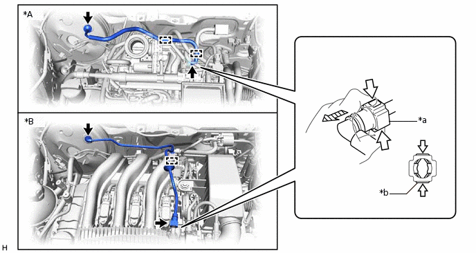
*A
for 1KR-FE
*B
for 1PP
*a
Vacuum Hose Assembly Connector
*b
Retainer

Pinch

Pull Off
for 1KR-FE:
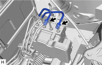
Disengage the 2 clamps to separate the vacuum hose assembly from the engine assembly.
for 1PP:
Disengage the clamp to separate the vacuum hose assembly from the engine assembly.
Disconnect the vacuum hose assembly from the intake manifold to remove it.
Pinch the retainer of the vacuum hose assembly, and then pull the vacuum hose assembly off of the intake manifold.
REMOVE BATTERY
for 1KR-FE:Click hereClick here
for 1PP:Click here
REMOVE BATTERY CLAMP SUB-ASSEMBLY
for 1KR-FE:Click hereClick here
for 1PP:Click here
REMOVE RELAY BLOCK BRACKET
SEPARATE CLUTCH RELEASE CABLE CLAMP (for 1PP)
SEPARATE BRAKE LINE
-
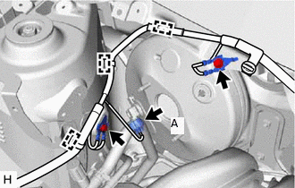
Using a union nut wrench, disconnect the 2 brake lines from the brake actuator assembly.
Disengage the 2 clamps to separate the 2 brake lines from the No. 2 brake tube clamp and No. 3 brake tube clamp.
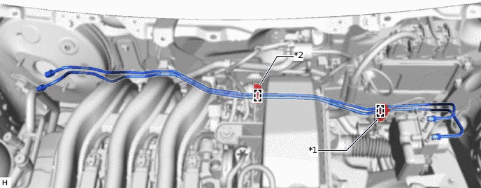
*1
No. 2 Brake Tube Clamp
*2
No. 3 Brake Tube Clamp
-
SEPARATE RADIATOR RESERVE TANK ASSEMBLY (for 1PP with Air Conditioning System)
-

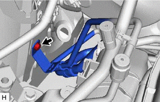
*a
Grommet
Remove the bolt.
Disengage the guide and grommet to separate the radiator reserve tank assembly as shown in the illustration.
-
SEPARATE AIR CONDITIONER HOSE AND ACCESSORY (for 1PP with Air Conditioning System)
-
Remove the bolt and separate the air conditioner hose and accessory.
Note:Do not deform the refrigerant lines.
-
SEPARATE ENGINE ROOM MAIN WIRE
-
for 1KR-FE with Stop and Start System, 1PP:
Disconnect the connector (A) from the vacuum sensor assembly.
Remove the 2 bolts and separate the 2 ground wires.
Disengage the 3 clamps to separate the engine room main wire from the vehicle body.
-
LOOSEN LOCK NUT
-
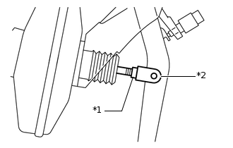
*1
Lock Nut
*2
Brake Master Cylinder Push Rod Clevis
Loosen the lock nut of the brake master cylinder push rod clevis.
-
REMOVE PUSH ROD PIN
REMOVE BRAKE BOOSTER ASSEMBLY
-
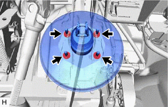
Remove the 4 nuts and push the brake booster assembly toward the engine compartment.
Note:Do not apply excessive force to the brake lines.
Remove the brake master cylinder push rod clevis and lock nut from the brake booster assembly.
Remove the brake booster assembly from the vehicle body.
Note:Do not apply excessive force to the brake lines or refrigerant lines.
-
REMOVE BRAKE BOOSTER GASKET