CAN COMMUNICATION SYSTEM(w/o Central Gateway ECU) TERMINALS OF ECU
Note
-
After turning the power switch off, waiting time may be required before disconnecting the cable from the negative (-) auxiliary battery terminal. Therefore, make sure to read the disconnecting the cable from the negative (-) auxiliary battery terminal notices before proceeding with work Click here.
-
Turn the power switch off before measuring the resistances between CAN main bus lines and between CAN branch lines.
-
Turn the power switch off before inspecting CAN bus lines for a ground short.
-
Before measuring the resistance of the CAN bus, turn the power switch off and leave the vehicle for 1 minute or more without operating the key or any switches, or opening or closing the doors. After that, disconnect the cable from the negative (-) auxiliary battery terminal and leave the vehicle for 1 minute or more before measuring the resistance.
-
This section describes the standard values for all CAN related components.
Tech Tips
-
Operating the power switch, any other switches or a door triggers related ECU and sensor communication on the CAN. This communication will cause the resistance value to change.
-
Even after DTCs are cleared, if a DTC is stored again after driving the vehicle for a while, the malfunction may be occurring due to vibration of the vehicle. In such a case, wiggling the ECUs or wire harness while performing the inspection below may help determine the cause of the malfunction.
-
CAN NO. 1 JUNCTION CONNECTOR (for LHD)
-
Check the CAN No. 1 junction connector (engine room main wire side).
Tech Tips
The following tables contain information about the items and buses connected via junction connectors. The junction connector may be used for multiple separate buses. In this case, the name of the bus will be shown below the name of the item that terminals are connected to. The bus name will be shown in brackets (example: (for Sub bus 12)).
-
Connection diagram
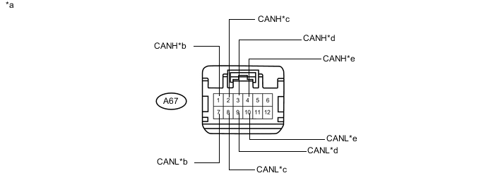
Text in Illustration *a Front view of wire harness connector
(to CAN No. 1 Junction Connector)
*b to ECM
(for V Bus)
*c to Brake Booster with Master Cylinder Assembly (Skid Control ECU)
(for V Bus)
*d to Brake Booster with Master Cylinder Assembly (Skid Control ECU)
(for Sub Bus 12)
*e to ECM
(for Sub Bus 12)
- - -
Check the connection diagram of the components which are connected to the CAN No. 1 junction connector.
Terminal No. (Symbol) Wiring Color Connected to A67-1 (CANH) P ECM
(for V bus)
A67-7 (CANL) V A67-2 (CANH) LG Brake booster with master cylinder assembly (Skid control ECU)
(for V bus)
A67-8 (CANL) L A67-3 (CANH) P Brake booster with master cylinder assembly (Skid control ECU)
(for Sub bus 12)
A67-9 (CANL) V A67-4 (CANH) B ECM
(for Sub bus 12)
A67-10 (CANL) W
-
-
Check the CAN No. 1 junction connector (instrument panel wire side).
-
Connection diagram
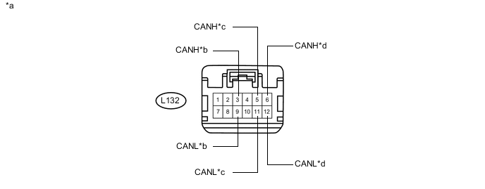
Text in Illustration *a Front view of wire harness connector
(to CAN No. 1 Junction Connector)
*b to CAN No. 5 Junction Connector
(for Sub Bus 12)
*c Main body ECU (Multiplex Network Body ECU)
(for V Bus)
*d to CAN No. 2 Junction Connector
(for V Bus)
-
Check the connection diagram of the components which are connected to the CAN No. 1 junction connector.
Terminal No. (Symbol) Wiring Color Connected to L132-3 (CANH) R CAN No. 5 junction connector
(for Sub bus 12)
L132-9 (CANL) Y L132-5 (CANH) SB Main body ECU (Multiplex network body ECU)
(for V bus)
L132-11 (CANL) W L132-6 (CANH) B CAN No. 2 junction connector
(for V bus)
L132-12 (CANL) W
-
-
-
CAN NO. 1 JUNCTION CONNECTOR (for RHD)
-
Check the CAN No. 1 junction connector (engine room main wire side).
Tech Tips
The following tables contain information about the items and buses connected via junction connectors. The junction connector may be used for multiple separate buses. In this case, the name of the bus will be shown below the name of the item that terminals are connected to. The bus name will be shown in brackets (example: (for Sub bus 12)).
-
Connection diagram
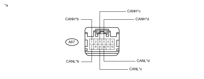
Text in Illustration *a Front view of wire harness connector
(to CAN No. 1 Junction Connector)
*b to Brake Booster with Master Cylinder Assembly (Skid Control ECU)
(for V Bus)
*c to Brake Booster with Master Cylinder Assembly (Skid Control ECU)
(for Sub Bus 12)
*d to ECM
(for Sub Bus 12)
-
Check the connection diagram of the components which are connected to the CAN No. 1 junction connector.
Terminal No. (Symbol) Wiring Color Connected to A67-1 (CANH) LG Brake booster with master cylinder assembly (Skid control ECU)
(for V bus)
A67-7 (CANL) L A67-3 (CANH) P Brake booster with master cylinder assembly (Skid control ECU)
(for Sub bus 12)
A67-9 (CANL) V A67-4 (CANH) B ECM
(for Sub bus 12)
A67-10 (CANL) W
-
-
Check the CAN No. 1 junction connector (instrument panel wire side).
-
Connection diagram
Text in Illustration *a Front view of wire harness connector
(to CAN No. 1 Junction Connector)
*b to CAN No. 5 Junction Connector
(for Sub Bus 12)
*c to CAN No. 2 Junction Connector
(for V Bus)
*d Combination Meter Sub-assembly
(for V Bus)
-
Check the connection diagram of the components which are connected to the CAN No. 1 junction connector.
Terminal No. (Symbol) Wiring Color Connected to L132-3 (CANH) R CAN No. 5 junction connector
(for Sub bus 12)
L132-9 (CANL) Y L132-5 (CANH) GR CAN No. 2 junction connector
(for V bus)
L132-11 (CANL) W L132-6 (CANH) SB Combination meter sub-assembly
(for V bus)
L132-12 (CANL) G
-
-
-
CAN NO. 2 JUNCTION CONNECTOR (for LHD)
-
Check the CAN No. 2 junction connector (instrument panel connector holder left side).
-
Connection diagram
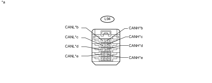
Text in Illustration *a Front view of wire harness connector
(to CAN No. 2 Junction Connector)
*b to CAN No. 3 Junction Connector
(for V Bus)
*c to CAN No. 1 Junction Connector
(for V Bus)
*d to Certification ECU (Smart Key ECU Assembly)
(for V Bus)
*e to Spiral Cable with Sensor Sub-assembly (Steering Angle Sensor)
(for V Bus)
- - -
Check the connection diagram of the components which are connected to the CAN No. 2 junction connector.
Terminal No. (Symbol) Wiring Color Connected to L94-2 (CANH) GR CAN No. 3 junction connector
(for V bus)
L94-1 (CANL) W L94-5 (CANH) B CAN No. 1 junction connector
(for V bus)
L94-4 (CANL) W L94-8 (CANH) B Certification ECU (Smart key ECU assembly)
(for V bus)
L94-7 (CANL) W L94-11 (CANH) B Spiral cable with sensor sub-assembly (Steering angle sensor)
(for V bus)
L94-10 (CANL) W
-
-
Check the CAN No. 2 junction connector (instrument panel connector holder right side).
-
Connection diagram
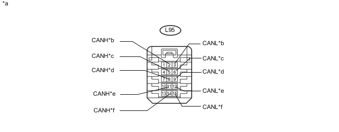
Text in Illustration *a Front view of wire harness connector
(to CAN No. 2 Junction Connector)
*b to Power Steering ECU Assembly
(for V Bus)
*c to Yaw Rate Sensor
(for V Bus)
*d to Airbag ECU Assembly
(for V Bus)
*e to Radio and Display Receiver Assembly
(for Radio and Display Type)
(for V Bus)
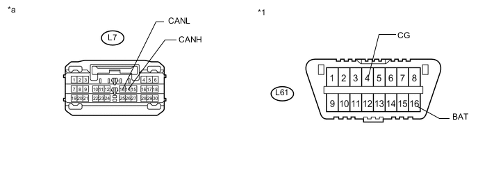
*f to DLC3
(for V Bus)
-
Check the connection diagram of the components which are connected to the CAN No. 2 junction connector.
Terminal No. (Symbol) Wiring Color Connected to L95-2 (CANH) R Power steering ECU assembly
(for V bus)
L95-3 (CANL) W L95-5 (CANH) B Yaw rate sensor
(for V bus)
L95-6 (CANL) W L95-8 (CANH) B Airbag ECU assembly
(for V bus)
L95-9 (CANL) W L95-11 (CANH) B Radio and display receiver assembly*
(for V bus)
L95-12 (CANL) W L95-14 (CANH) B DLC3
(for V bus)
L95-15 (CANL) W *: for Radio and Display Type
-
-
-
CAN NO. 2 JUNCTION CONNECTOR (for RHD)
-
Check the CAN No. 2 junction connector (instrument panel connector holder left side).
-
Connection diagram
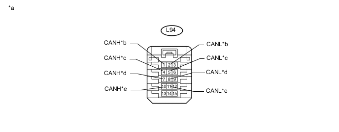
Text in Illustration *a Front view of wire harness connector
(to CAN No. 2 Junction Connector)
*b to CAN No. 1 Junction Connector
(for V Bus)
*c to CAN No. 3 Junction Connector
(for V Bus)
*d to Certification ECU (Smart Key ECU Assembly)
(for V Bus)
*e to Spiral Cable with Sensor Sub-assembly (Steering Angle Sensor)
(for V Bus)
- - -
Check the connection diagram of the components which are connected to the CAN No. 2 junction connector.
Terminal No. (Symbol) Wiring Color Connected to L94-1 (CANH) GR CAN No. 1 junction connector
(for V bus)
L94-2 (CANL) W L94-4 (CANH) B CAN No. 3 junction connector
(for V bus)
L94-5 (CANL) W L94-7 (CANH) B Certification ECU (Smart key ECU assembly)
(for V bus)
L94-8 (CANL) W L94-10 (CANH) B Spiral cable with sensor sub-assembly (Steering angle sensor)
(for V bus)
L94-11 (CANL) W
-
-
Check the CAN No. 2 junction connector (instrument panel connector holder right side).
-
Connection diagram
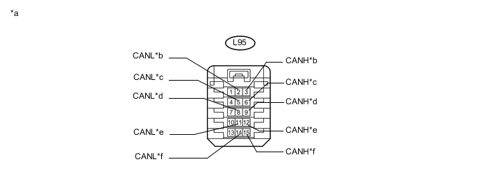
Text in Illustration *a Front view of wire harness connector
(to CAN No. 2 Junction Connector)
*b to Power Steering ECU Assembly
(for V Bus)
*c to Yaw Rate Sensor
(for V Bus)
*d to Airbag ECU Assembly
(for V Bus)
*e
-
to Navigation Receiver Assembly
(for Navigation Receiver Type)
-
to Radio and Display Receiver Assembly
(for Radio and Display Type)
(for V Bus)
*f to DLC3
(for V Bus)
-
-
Check the connection diagram of the components which are connected to the CAN No. 2 junction connector.
Terminal No. (Symbol) Wiring Color Connected to L95-3 (CANH) R Power steering ECU assembly
(for V bus)
L95-2 (CANL) W L95-6 (CANH) B Yaw rate sensor
(for V bus)
L95-5 (CANL) W L95-9 (CANH) B Airbag ECU assembly
(for V bus)
L95-8 (CANL) W L95-12 (CANH) B
-
Navigation receiver assembly*1
-
Radio and display receiver assembly*2
(for V bus)
L95-11 (CANL) W L95-15 (CANH) B DLC3
(for V bus)
L95-14 (CANL) W *1: for Navigation Receiver Type
*2: for Radio and Display Type
-
-
-
-
CAN NO. 3 JUNCTION CONNECTOR (for LHD)
-
Check the CAN No. 3 junction connector (engine room main wire side).
-
Connection diagram
Text in Illustration *a Front view of wire harness connector
(to CAN No. 3 Junction Connector)
*b to Transmission Control ECU Assembly
(for V Bus)
-
Check the connection diagram of the components which are connected to the CAN No. 3 junction connector.
Terminal No. (Symbol) Wiring Color Connected to A68-1 (CANH) Y Transmission control ECU assembly
(for V bus)
A68-7 (CANL) BR
-
-
Check the CAN No. 3 junction connector (instrument panel wire side).
-
Connection diagram
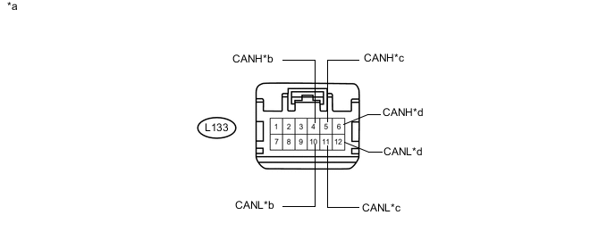
Text in Illustration *a Front view of wire harness connector
(to CAN No. 3 Junction Connector)
*b to Power Management Control ECU
(for V Bus)
*c to CAN No. 2 Junction Connector
(for V Bus)
*d to Combination Meter Sub-assembly
(for V Bus)
-
Check the connection diagram of the components which are connected to the CAN No. 3 junction connector.
Terminal No. (Symbol) Wiring Color Connected to L133-4 (CANH) V Power management control ECU
(for V bus)
L133-10 (CANL) P L133-5 (CANH) GR CAN No. 2 junction connector
(for V bus)
L133-11 (CANL) W L133-6 (CANH) SB Combination meter sub-assembly
(for V bus)
L133-12 (CANL) G
-
-
-
CAN NO. 3 JUNCTION CONNECTOR (for RHD)
-
Check the CAN No. 3 junction connector (engine room main wire side).
-
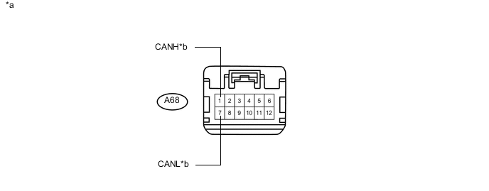
Connection diagram
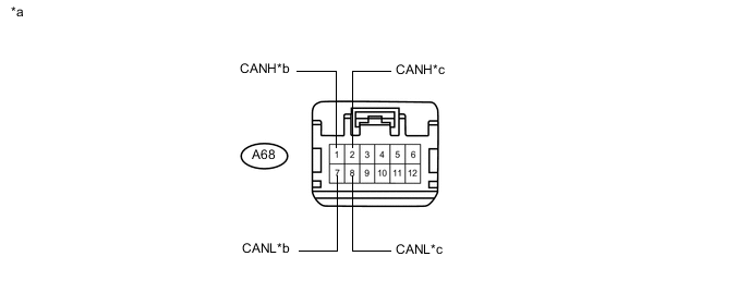
Text in Illustration *a Front view of wire harness connector
(to CAN No. 3 Junction Connector)
*b ECM
(for V Bus)
*c to Transmission Control ECU Assembly
(for V Bus)
- - -
Check the connection diagram of the components which are connected to the CAN No. 3 junction connector.
Terminal No. (Symbol) Wiring Color Connected to A68-1 (CANH) P ECM
(for V bus)
A68-7 (CANL) V A68-2 (CANH) Y Transmission control ECU assembly
(for V bus)
A68-8 (CANL) BR
-
-
Check the CAN No. 3 junction connector (instrument panel wire side).
-
Connection diagram
Text in Illustration *a Front view of wire harness connector
(to CAN No. 3 Junction Connector)
*b to Power Management Control ECU
(for V Bus)
*c to Main body ECU (Multiplex Network Body ECU)
(for V Bus)
*d to CAN No. 2 Junction Connector
(for V Bus)
-
Check the connection diagram of the components which are connected to the CAN No. 3 junction connector.
Terminal No. (Symbol) Wiring Color Connected to L133-4 (CANH) V Power management control ECU
(for V bus)
L133-10 (CANL) P L133-5 (CANH) SB Main body ECU (Multiplex network body ECU)
(for V bus)
L133-11 (CANL) W L133-6 (CANH) B CAN No. 2 junction connector
(for V bus)
L133-12 (CANL) W
-
-
-
CAN NO. 4 JUNCTION CONNECTOR
-
Check the CAN No. 4 junction connector.
Tech Tips
Connectors that connect to the CAN junction connector can be distinguished by the color of their CAN bus lines. When the connectors have been disconnected from the CAN junction connector, reconnecting the connectors to non-original positions on the CAN junction connector does not affect system performance. However, it is preferred to reconnect the connectors to their original positions to avoid negative effects on the wiring such as tension on the wire harnesses, and to make future maintenance easier.
-
Connection diagram
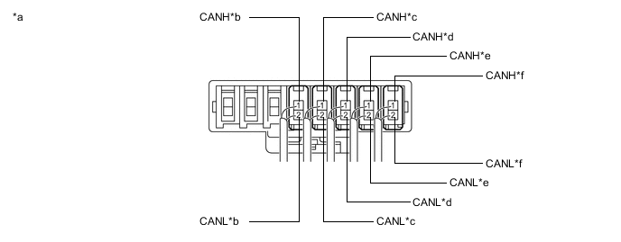
Text in Illustration *a Component with harness connected
(CAN No. 4 Junction Connector)
*b to Lane Departure Warning Camera
(w/ Lane Departure Alert System)
(for Sub Bus 11)
*c to Power Management Control ECU
(for Sub Bus 11)
*d to Parking assist ECU
(w/ Intelligent Parking Assist System)
(for Sub Bus 11)
*e to Driving Support ECU Assembly
(w/ Pre-crash Safety System)
(for Sub Bus 11)
*f to CAN No. 1 Junction Terminal
(for Sub Bus 11)
-
-
Check the connection diagram of the components which are connected to the CAN No. 4 junction connector.
Terminal No. (Symbol) Wiring Color Connected to L185-1 (CANH) B Lane departure warning camera*1
(for Sub bus 11)
L185-2 (CANL) W L184-1 (CANH) B Power management control ECU
(for Sub bus 11)
L184-2 (CANL) G L183-1 (CANH) B Parking assist ECU*2
(for Sub bus 11)
L183-2 (CANL) L L182-1 (CANH) B Driving support ECU assembly*3
(for Sub bus 11)
L182-2 (CANL) R L181-1 (CANH) B CAN No. 1 junction terminal
(for Sub bus 11)
L181-2 (CANL) Y *1: w/ Lane Departure Alert System
*2: w/ Intelligent Parking Assist System
*3: w/ Pre-crash Safety System
-
-
CAN NO. 5 JUNCTION CONNECTOR
-
Check the CAN No. 5 junction connector (instrument panel connector holder left side).
-
Connection diagram
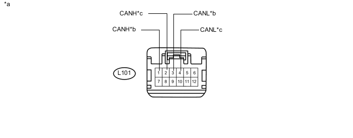
Text in Illustration *a Front view of wire harness connector
(to CAN No. 5 Junction Connector)
*b to Air Conditioning Amplifier Assembly
(for Sub Bus 12)
*c to CAN No. 1 Junction Connector
(for Sub Bus 12)
- - -
Check the connection diagram of the components which are connected to the CAN No. 5 junction connector.
Terminal No. (Symbol) Wiring Color Connected to L101-1 (CANH) B Air conditioning amplifier assembly
(for Sub bus 12)
L101-3 (CANL) W L101-2 (CANH) R CAN No. 1 junction connector
(for Sub bus 12)
L101-4 (CANL) Y
-
-
Check the CAN No. 5 junction connector (instrument panel connector holder right side).
-
Connection diagram
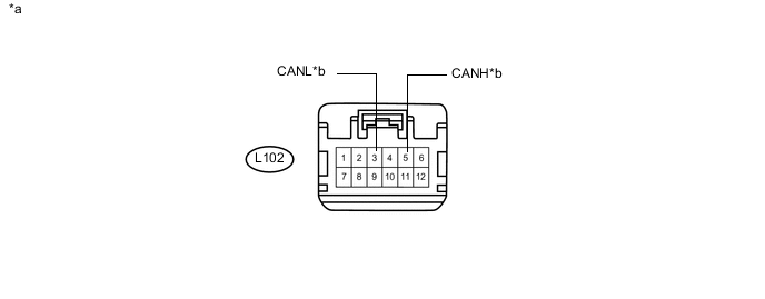
Text in Illustration *a Front view of wire harness connector
(to CAN No. 5 Junction Connector)
*b to Power Management Control ECU
(for Sub Bus 12)
-
Check the connection diagram of the components which are connected to the CAN No. 5 junction connector.
Terminal No. (Symbol) Wiring Color Connected to L102-5 (CANH) B Power management control ECU
(for Sub bus 12)
L102-3 (CANL) W
-
-
-
CAN No. 1 JUNCTION TERMINAL
-
Check the CAN No. 1 junction terminal.
-
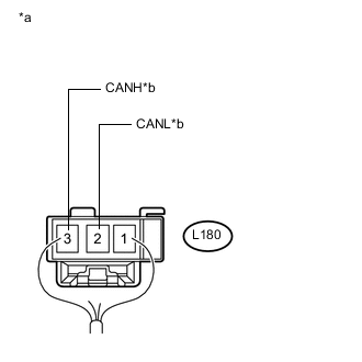
Text in Illustration *a Rear view of wire harness connector
(to CAN No. 1 Junction Terminal)
*b to CAN No. 4 Junction Connector
(for Sub Bus 11)
Connection diagram
-
Check the connection diagram of the components which are connected to the CAN No. 1 junction terminal.
Terminal No. (Symbol) Wiring Color Connected to L180-3 (CANH) B CAN No. 4 junction connector
(for Sub bus 11)
L180-2 (CANL) Y
-
-
-
DLC3
-
Measure the resistance according to the value(s) in the table below.
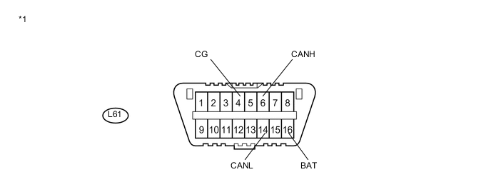
Text in Illustration *1 DLC3 - -
-
-
POWER MANAGEMENT CONTROL ECU
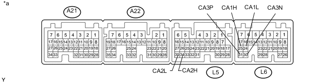
Text in Illustration *a Component without harness connected
(Power Management Control ECU)
- -
-
Disconnect the cable from the negative (-) auxiliary battery terminal.
-
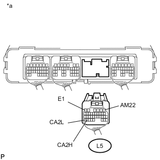
Text in Illustration *a Rear view of wire harness connector
(to Power Management Control ECU)
Disconnect the L5 power management control ECU connector.
-
Measure the resistance according to the value(s) in the table below.
-
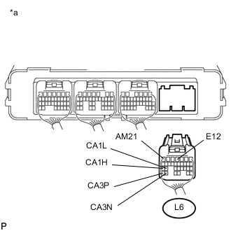
Text in Illustration *a Rear view of wire harness connector
(to Power Management Control ECU)
Disconnect the L6 power management control ECU connector.
-
Measure the resistance according to the value(s) in the table below.
-
-
ECM
Text in Illustration *a Component without harness connected
(ECM)
- -
-
Disconnect the cable from the negative (-) auxiliary battery terminal.
-
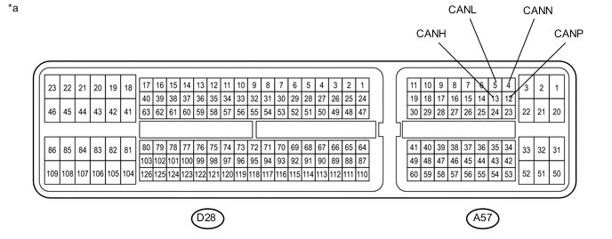
Disconnect the A57 and D28 ECM connectors.
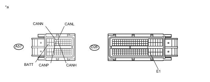
Text in Illustration *a Front view of wire harness connector
(to ECM)
- - -
Measure the resistance according to the value(s) in the table below.
-
-
TRANSMISSION CONTROL ECU ASSEMBLY
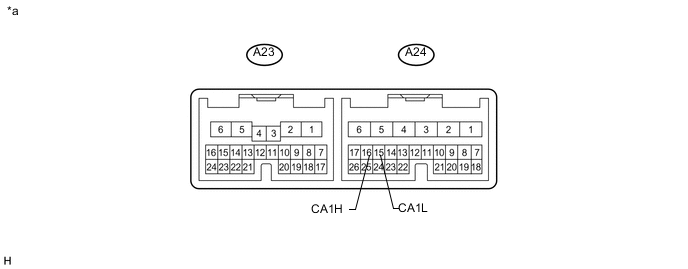
Text in Illustration *a Component without harness connected
(Transmission Control ECU Assembly)
- -
-
Disconnect the cable from the negative (-) auxiliary battery terminal.
-
Text in Illustration *a Front view of wire harness connector
(to Transmission Control ECU Assembly)
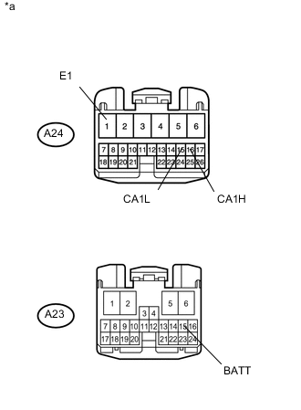
Disconnect the A23 and A24 transmission control ECU assembly connectors.
-
Measure the resistance according to the value(s) in the table below.
-
-
BRAKE BOOSTER WITH MASTER CYLINDER ASSEMBLY (SKID CONTROL ECU)
-
Disconnect the cable from the negative (-) auxiliary battery terminal.
-
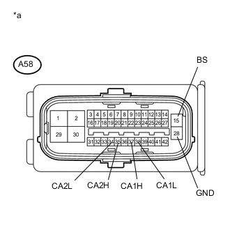
Text in Illustration *a Front view of wire harness connector
(to Brake Booster with Master Cylinder Assembly)
Disconnect the A58 brake booster with master cylinder assembly (skid control ECU) connector.
-
Measure the resistance according to the value(s) in the table below.
-
-
AIRBAG ECU ASSEMBLY
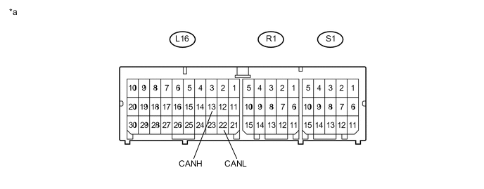
Text in Illustration *a Component without harness connected
(Airbag ECU Assembly)
- -
-
Disconnect the cable from the negative (-) auxiliary battery terminal.
-
Disconnect the L16 airbag ECU assembly connector.
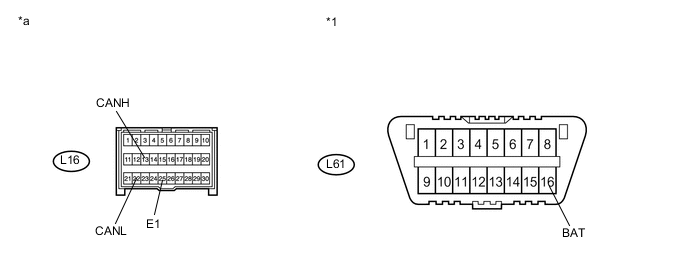
Text in Illustration *1 DLC3 - - *a Front view of wire harness connector
(to Airbag ECU Assembly)
- - -
Measure the resistance according to the value(s) in the table below.
-
-
INSTRUMENT PANEL JUNCTION BLOCK ASSEMBLY AND MAIN BODY ECU (MULTIPLEX NETWORK BODY ECU)
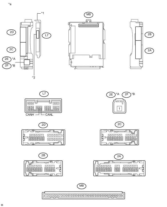
Text in Illustration *A for LHD *B for RHD *1 Main Body ECU (Multiplex Network Body ECU) *2 1 connector *a Component without harness connected
(Instrument Panel Junction Block Assembly and Main Body ECU (Multiplex Network Body ECU))
- - 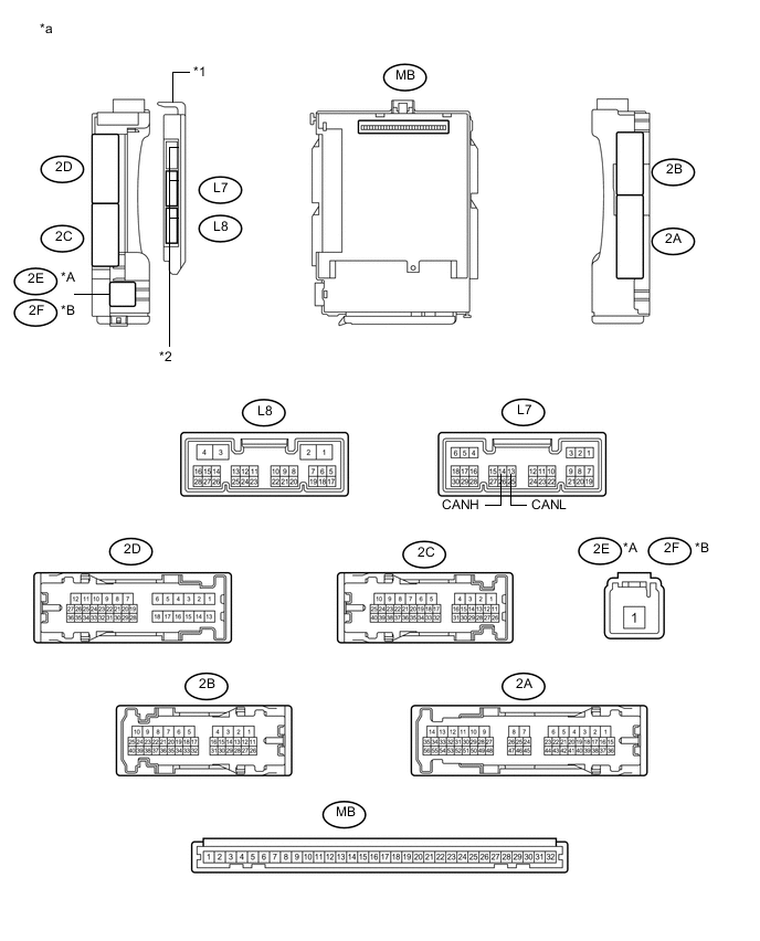
Text in Illustration *A for LHD *B for RHD *1 Main Body ECU (Multiplex Network Body ECU) *2 3 connectors *a Component without harness connected
(Instrument Panel Junction Block Assembly and Main Body ECU (Multiplex Network Body ECU))
- -
-
Disconnect the cable from the negative (-) auxiliary battery terminal.
-
Disconnect the L7 main body ECU (multiplex network body ECU) connector.
Text in Illustration *1 DLC3 - - *a Front view of wire harness connector
(to Main Body ECU (Multiplex Network Body ECU))
- - -
Measure the resistance according to the value(s) in the table below.
-
-
SPIRAL CABLE WITH SENSOR SUB-ASSEMBLY (STEERING ANGLE SENSOR)
-
Disconnect the cable from the negative (-) auxiliary battery terminal.
-
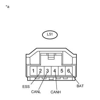
Text in Illustration *a Front view of wire harness connector
(to Spiral Cable with Sensor Sub-assembly (Steering Angle Sensor))
Disconnect the L51 spiral cable with sensor sub-assembly (steering angle sensor) connector.
-
Measure the resistance according to the value(s) in the table below.
-
-
YAW RATE SENSOR
-
Disconnect the cable from the negative (-) auxiliary battery terminal.
-
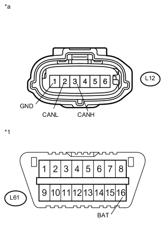
Text in Illustration *1 DLC3 *a Front view of wire harness connector
(to Yaw Rate Sensor)
Disconnect the L12 yaw rate sensor connector.
-
Measure the resistance according to the value(s) in the table below.
-
-
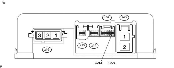
POWER STEERING ECU ASSEMBLY
Text in Illustration *a Component without harness connected
(Power Steering ECU Assembly)
- -
-
Disconnect the cable from the negative (-) auxiliary battery terminal.
-
Disconnect the A27 and L54 power steering ECU assembly connectors.
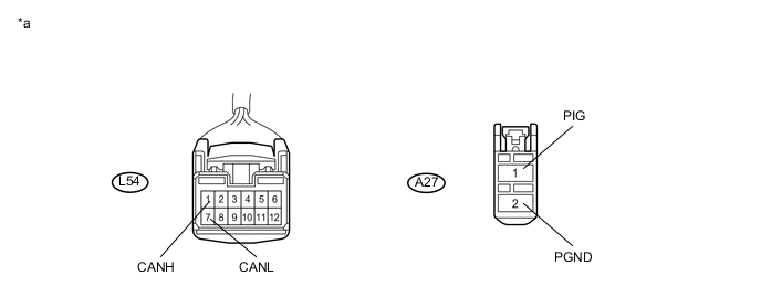
Text in Illustration *a Front view of wire harness connector
(to Power Steering ECU Assembly)
- - -
Measure the resistance according to the value(s) in the table below.
-
-
CERTIFICATION ECU (SMART KEY ECU ASSEMBLY)
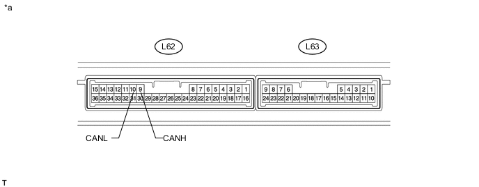
Text in Illustration *a Component without harness connected
(Certification ECU (Smart Key ECU Assembly))
- -
-
Disconnect the cable from the negative (-) auxiliary battery terminal.
-
Disconnect the L62 certification ECU (smart key ECU assembly) connector.
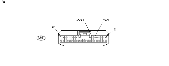
Text in Illustration *a Front view of wire harness connector
(to Certification ECU (Smart Key ECU Assembly))
- - -
Measure the resistance according to the value(s) in the table below.
-
-
RADIO AND DISPLAY RECEIVER ASSEMBLY (for Radio and Display Type)

Text in Illustration *A w/ Rear View Monitor System *B w/ Intelligent Parking Assist System *a Component without harness connected
(Radio and Display Receiver Assembly)
- -
-
Disconnect the cable from the negative (-) auxiliary battery terminal.
-
Disconnect the L35 and L167 radio and display receiver assembly connectors.
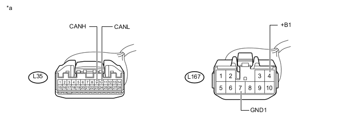
Text in Illustration *a Front view of wire harness connector
(to Radio and Display Receiver Assembly)
- - -
Measure the resistance according to the value(s) in the table below.
-
-
NAVIGATION RECEIVER ASSEMBLY (for Navigation Receiver Type)
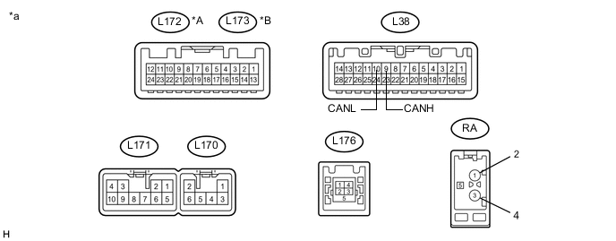
Text in Illustration *A w/o Intelligent Parking Assist System *B w/ Intelligent Parking Assist System *a Component without harness connected
(Navigation Receiver Assembly)
- -
-
Disconnect the cable from the negative (-) auxiliary battery terminal.
-
Disconnect the L38 and L171 navigation receiver assembly connectors.
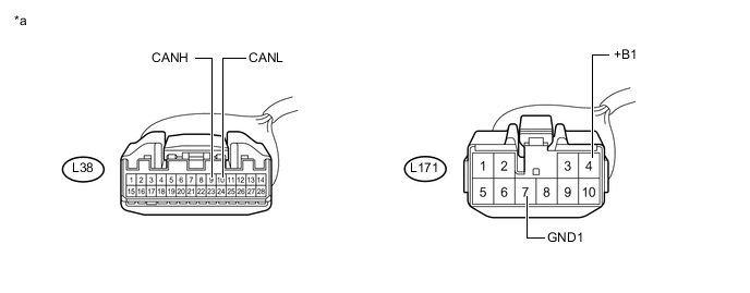
Text in Illustration *a Front view of wire harness connector
(to Navigation Receiver Assembly)
- - -
Measure the resistance according to the value(s) in the table below.
-
-
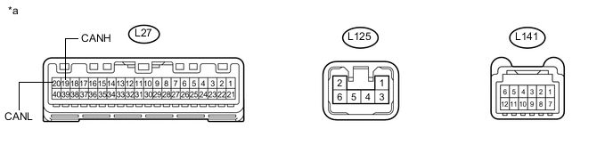
COMBINATION METER SUB-ASSEMBLY
Text in Illustration *a Component without harness connected
(Combination Meter Sub-assembly)
- -
-
Disconnect the cable from the negative (-) auxiliary battery terminal.
-
Disconnect the L27 combination meter sub-assembly connector.
Text in Illustration *a Front view of wire harness connector
(to Combination Meter Sub-assembly)
- - -
Measure the resistance according to the value(s) in the table below.
-
-
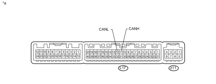
AIR CONDITIONING AMPLIFIER ASSEMBLY
Text in Illustration *a Component without harness connected
(Air Conditioning Amplifier Assembly)
- -
-
Disconnect the cable from the negative (-) auxiliary battery terminal.
-
Disconnect the L17 air conditioning amplifier assembly connector.
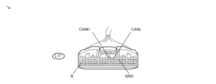
Text in Illustration *a Front view of wire harness connector
(to Air Conditioning Amplifier Assembly)
- - -
Measure the resistance according to the value(s) in the table below.
-
-
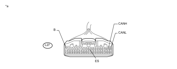
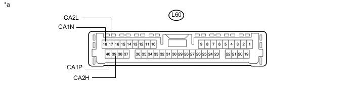
DRIVING SUPPORT ECU ASSEMBLY (w/ Pre-crash Safety System)
Text in Illustration *a Component without harness connected
(Driving Support ECU Assembly)
- -
-
Disconnect the cable from the negative (-) auxiliary battery terminal.
-
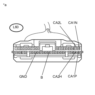
Text in Illustration *a Front view of wire harness connector
(to Driving Support ECU Assembly)
Disconnect the L60 driving support ECU assembly connector.
-
Measure the resistance according to the value(s) in the table below.
-
-
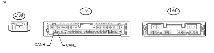
PARKING ASSIST ECU (w/ Intelligent Parking Assist System)
Text in Illustration *a Component without harness connected
(Parking Assist ECU)
- -
-
Disconnect the cable from the negative (-) auxiliary battery terminal.
-
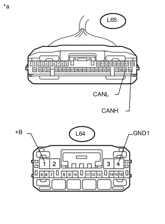
Text in Illustration *a Front view of wire harness connector
(to Parking Assist ECU)
Disconnect the L64 and L65 parking assist ECU connectors.
-
Measure the resistance according to the value(s) in the table below.
-
-
MILLIMETER WAVE RADAR SENSOR ASSEMBLY (w/ Pre-crash Safety System)
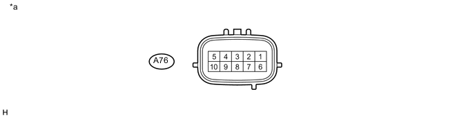
Text in Illustration *a Component without harness connected
(Millimeter Wave Radar Sensor Assembly)
- -
-
Disconnect the cable from the negative (-) auxiliary battery terminal.
-
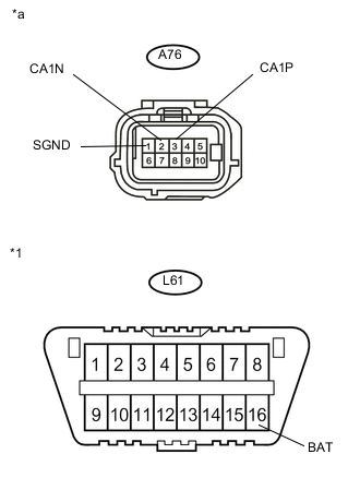
Text in Illustration *1 DLC3 *a Front view of wire harness connector
(to Millimeter Wave Radar Sensor Assembly)
Disconnect the A76 millimeter wave radar sensor assembly connector.
-
Measure the resistance according to the value(s) in the table below.
-
-
LANE DEPARTURE WARNING CAMERA (w/ Lane Departure Alert System)
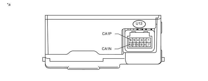
Text in Illustration *a Component without harness connected
(Lane Departure Warning Camera)
- -
-
Disconnect the cable from the negative (-) auxiliary battery terminal.
-
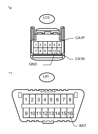
Text in Illustration *1 DLC3 *a Front view of wire harness connector
(to Lane Departure Warning Camera)
Disconnect the U13 lane departure warning camera connector.
-
Measure the resistance according to the value(s) in the table below.
-