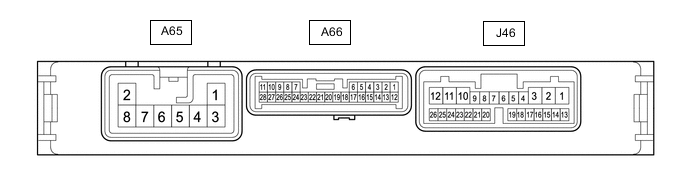
STOP AND START SYSTEM TERMINALS OF ECU
-
ENGINE STOP AND START ECU
-
Disconnect the A65, A66 and J46 engine stop and start ECU connectors.
-
Measure the resistance and voltage according to the value(s) in the table below.
Terminal No. (Symbol) Wiring Color Terminal Description Condition Specified Condition A65-1 (BIN2) - Body ground W - Body ground Battery Always 9.5 to 14 V A65-2 (GND2) - Body ground W-B - Body ground Ground Always Below 1 Ω A65-3 (BIN1) - Body ground B - Body ground Battery Always 9.5 to 14 V A65-8 (GND1) - Body ground W-B - Body ground Ground Always Below 1 Ω A66-1 (+B) - Body ground Y - Body ground Power source of engine stop and start ECU Engine switch on (IG) 9.5 to 14 V A66-6 (DGND) - Body ground W-B - Body ground Ground Always Below 1 Ω A66-10 (NE) - Body ground V - Body ground Engine speed signal from ECM Always 10 kΩ or higher J46-13 (CANH) - Body ground SB - Body ground CAN communication Always 200 Ω or higher J46-14 (CANL) - Body ground W - Body ground CAN communication Always 200 Ω or higher J46-18 (IG2) - Body ground V - Body ground Engine switch signal Engine switch on (IG) 9.5 to 14 V J46-19 (ACC) - Body ground R - Body ground Engine switch signal Engine switch on (ACC) 9.5 to 14 V J46-20 (ILL) - Body ground G - Body ground Headlight dimmer switch (light control switch) tail signal input Headlight dimmer switch (light control switch) in tail or head position 9.5 to 14 V J46-21 (IG1) - Body ground Y - Body ground Engine switch signal Engine switch on (IG) 9.5 to 14 V -
Reconnect the A65, A66 and J46 engine stop and start ECU connectors.
-
Measure the resistance and voltage according to the value(s) in the table below.
Terminal No. (Symbol) Wiring Color Terminal Description Condition Specified Condition A65-6 (OP21) - A66-6 (DGND) G - W-B Oil pump with motor assembly (automatic transaxle assembly) drive power source signal Either of the following conditions is met:
-
Engine stopped by stop and start control
-
Engine switch on (IG) (engine not running) and Active Test "AT Oil Pump (Lo)" being performed
10.5 to 16 V A66-3 (BRE2) - Body ground G - Body ground Ground (vacuum sensor assembly) Always Below 1 Ω A66-7 (BNT1) - A66-6 (DGND) B - W-B Engine hood courtesy switch (Hood lock assembly) signal
-
Engine switch on (IG)
-
Engine stopped
-
Engine hood closed
0 to 1.5 V
-
Engine switch on (IG)
-
Engine stopped
-
Engine hood open
8 to 14 V A66-9 (OPM1) - A66-6 (DGND) L - W-B Oil pump with motor assembly (automatic transaxle assembly) directions signal Either of the following conditions is met:
-
Engine stopped by stop and start control
-
Engine switch on (IG) (engine not running) and Active Test "AT Oil Pump (Lo)" being performed
Pulse generation
(see waveform 1)
A66-10 (NE) - A66-6 (DGND) V - W-B Engine speed signal from ECM Idling after engine warmed up Pulse generation
(see waveform 2)
A66-13 (PB) - A66-3 (BRE2) L - G Vacuum sensor assembly signal
-
Engine switch on (IG)
-
Absolute pressure of 40 kPa (300 mmHg, 11.8 in.Hg) applied to vacuum sensor assembly
1.6 to 2.0 V
-
Engine switch on (IG)
-
Absolute pressure of 60 kPa (450 mmHg, 17.7 in.Hg) applied to vacuum sensor assembly
2.2 to 2.6 V
-
Engine switch on (IG)
-
Atmospheric pressure applied to vacuum sensor assembly
3.4 to 3.8 V A66-14 (BRVC) - A66-6 (DGND) B - W-B Vacuum sensor assembly power supply
-
Engine switch on (IG)
-
Engine stopped
4.5 to 5.5 V A66-17 (CLL) - A66-6 (DGND) V - W-B Park/neutral position switch assembly signal
-
Engine switch on (IG)
-
Shift lever not in P or N
8 to 14 V
-
Engine switch on (IG)
-
Shift lever in P or N
Below 3.0 V A66-19 (DON2) - A66-6 (DGND) W - W-B Eco-run vehicle converter assembly (external backup boost converter) signal Engine running Pulse generation
(see waveform 3)
A66-21 (STA) - A66-6 (DGND) B - W-B Starter pinion operation signal Cranking 6.0 V or more A66-23 (STA2) - A66-6 (DGND) B - W-B Starter motor operation signal Cranking 6.0 V or more A66-27 (NOPM) - A66-6 (DGND) W - W-B Oil pump with motor assembly (automatic transaxle assembly) speed signal Either of the following conditions is met:
-
Engine stopped by stop and start control
-
Engine switch on (IG) (engine not running) and Active Test "AT Oil Pump (Lo)" being performed
Pulse generation
(see waveform 4)
J46-1 (IG31) - A66-6 (DGND) GR - W-B Backup boost converter signal Engine switch on (IG) 10.5 to 16 V J46-2 (B41) -A66-6 (DGND) BE - W-B Backup boost converter signal Always 10.5 to 16 V J46-3 (IG41) - A66-6 (DGND) SB - W-B Backup boost converter signal Engine switch on (IG) 10.5 to 16 V J46-5 (ECAN) -A66-6 (DGND) Y - W-B Stop and start system cancel switch (combination switch assembly) signal
-
Engine switch on (IG)
-
Stop and start system cancel switch (combination switch assembly) pressed
0 to 1.5 V
-
Engine switch on (IG)
-
Stop and start system cancel switch (combination switch assembly) not pressed
8 to 14 V J46-6 (IG11) - A66-6 (DGND) P - W-B Backup boost converter signal Engine switch on (IG) 10.5 to 16 V J46-10 (IG12) - A66-6 (DGND) GR - W-B Backup boost converter signal Engine switch on (IG) 10.5 to 16 V J46-11 (B43) - A66-6 (DGND) L - W-B Backup boost converter signal Always 10.5 to 16 V J46-12 (B42) - A66-6 (DGND) LG - W-B Backup boost converter signal Always 10.5 to 16 V J46-15 (AC42) - A66-6 (DGND) L - W-B Backup boost converter signal Engine switch on (ACC) 10.5 to 16 V J46-16 (B12) - A66-6 (DGND) B - W-B Backup boost converter signal Always 10.5 to 16 V J46-18 (IG2) - A66-6 (DGND) V - W-B Engine switch signal Engine switch on (ACC) Below 1 V Engine switch on (IG) 9.5 to 14 V J46-19 (ACC) - A66-6 (DGND) R - W-B Engine switch signal Engine switch off Below 1 V Engine switch on (ACC) 9.5 to 14 V J46-21 (IG1) - A66-6 (DGND) Y - W-B Engine switch signal Engine switch on (ACC) Below 1 V Engine switch on (IG) 9.5 to 14 V J46-24 (AC41) - A66-6 (DGND) LG*1, SB*2 - W-B Backup boost converter signal Engine switch on (ACC) 10.5 to 16 V J46-25 (IL41) - A66-6 (DGND) G - W-B Backup boost converter signal Headlight dimmer switch (light control switch) in tail or head position 10.5 to 16 V J46-26 (IG13) - A66-6 (DGND) B - W-B Backup boost converter signal Engine switch on (IG) 10.5 to 16 V
-
*1: RHD
-
*2: LHD
-
-
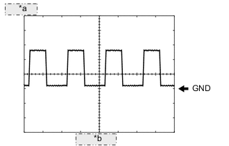
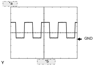
*a 5 V/DIV. *b 5 ms./DIV. Waveform 1
Item Content Tester Connection A66-9 (OPM1) - A66-6 (DGND) Tool Setting 5 V/DIV.,5 ms./DIV. Condition Either of the following conditions is met:
-
Engine stopped by stop and start control
-
Engine switch on (IG) (engine not running) and Active Test "AT Oil Pump (Lo)" being performed
-
-
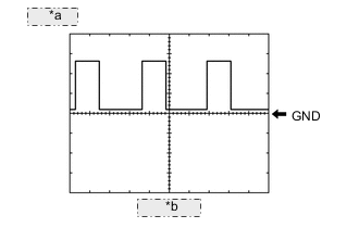
*a 5 V/DIV. *b 2 ms./DIV. Waveform 2
Item Content Tester Connection A66-10 (NE) - A66-6 (DGND) Tool Setting 5 V/DIV., 2 ms./DIV. Condition Idling after engine warmed up -
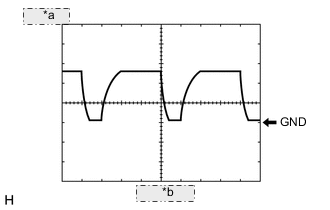
*a 5 V/DIV. *b 2 ms./DIV. Waveform 3
Item Content Tester Connection A66-19 (DON2) - A66-6 (DGND) Tool Setting 5 V/DIV., 2 ms./DIV. Condition Engine running -
*a 5 V/DIV. *b 5 ms./DIV. Waveform 4
Item Content Tester Connection A66-27 (NOPM) - A66-6 (DGND) Tool Setting 5 V/DIV.,5 ms./DIV. Condition Either of the following conditions is met:
-
Engine stopped by stop and start control
-
Engine switch on (IG) (engine not running) and Active Test "AT Oil Pump (Lo)" being performed
-
-