MONOLITHIC CONVERTER INSTALLATION
PROCEDURE
INSTALL EXHAUST MANIFOLD CONVERTER SUB-ASSEMBLY
-
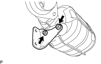
Temporarily install the manifold stay with the 2 nuts.
-
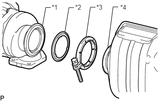
*1
Turbocharger Sub-assembly
*2
Gasket
*3
V-band Clamp
*4
Exhaust Manifold Converter Sub-assembly
Temporarily install the exhaust manifold converter sub-assembly and engine bracket with the 3 nuts, 3 bolts, a new V-band clamp and a new gasket.
Tighten the engine bracket with the 3 bolts.
19 N*m
194 kgf*cm
14 ft.*lbf
-
Temporarily install the manifold stay with the 2 bolts.
-
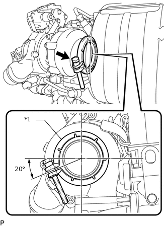
*1
V-band Clamp
Align the V-band clamp as shown in the illustration and temporarily install it.
3.0 N*m
31 kgf*cm
27 in.*lbf
Tip:To prevent the V-band clamp from interfering with the No. 1 manifold converter insulator, temporarily install the V-band clamp at the angle shown in the illustration.
-
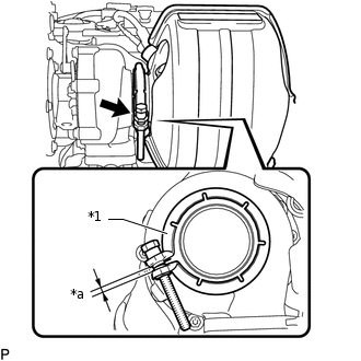
*1
V-band Clamp
*a
Clearance
Tighten the V-band clamp.
15 N*m
153 kgf*cm
11 ft.*lbf
Check the clearance of the V-band clamp.
Note:Do not reuse a V-band clamp that has been tightened to the specified torque.
Tip:After tightening the V-band clamp to the specified torque, check that the clearance is within 0 to 3.5 mm (0 to 0.138 in.). If the result is not as specified, reinstall the exhaust manifold converter sub-assembly as the installation position is incorrect.
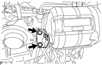
Tighten the 5 nuts, 2 bolts and exhaust manifold converter sub-assembly in the order shown in the illustration.
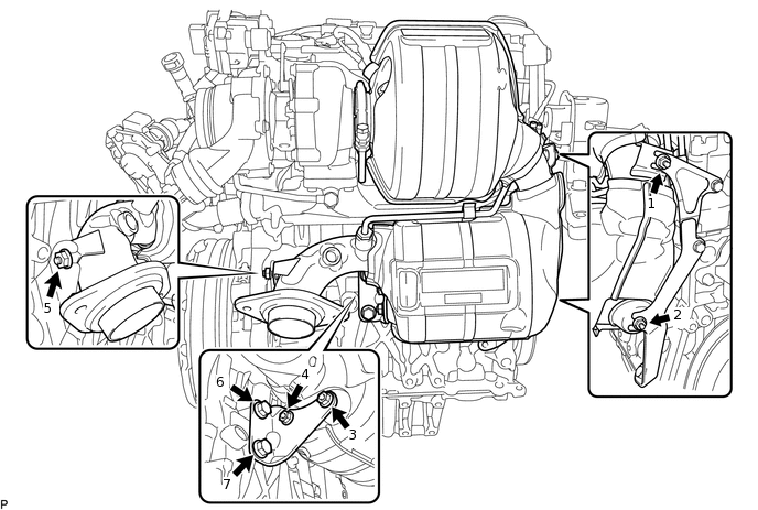
for Bolt
38 N*m
387 kgf*cm
28 ft.*lbf
for Nut
19 N*m
194 kgf*cm
14 ft.*lbf
-
INSTALL NO. 1 EXHAUST MANIFOLD HEAT INSULATOR
Install the No. 1 exhaust manifold heat insulator with the 2 bolts.
8.0 N*m
82 kgf*cm
71 in.*lbf
Attach the 2 clamps and connect the engine wire.
INSTALL FRONT EXHAUST PIPE ASSEMBLY
-
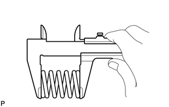
Using a vernier caliper, measure the free length of the compression springs.
Minimum Free Length (front)
41.5 mm (1.63 in.)
Minimum Free Length (rear)
38.5 mm (1.52 in.)
If the free length is less than minimum, replace the compression spring.
-
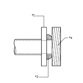
*1
Exhaust Manifold Converter Sub-assembly and Front Exhaust Pipe Assembly
*2
Gasket
*a
Wooden Block
Using a plastic hammer and wooden block, tap in 2 new gaskets until its surface is flush with the exhaust manifold converter sub-assembly and front exhaust pipe sub-assembly.
Note:Be sure to install the gasket in the correct direction.
Do not reuse the gasket.
Do not damage the gasket.
Do not push in the gasket by using the exhaust pipe when connecting it.
Connect the front exhaust pipe assembly to the 2 exhaust pipe supports.
-
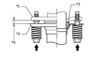
*1
Exhaust Manifold Converter Sub-assembly or Front Exhaust Pipe Assembly
*2
Front Exhaust Pipe Assembly or tail exhaust pipe assembly
*3
Gasket
*a
Space between Flanges: 8.5 mm (0.335 in.)
Install the front exhaust pipe assembly to the exhaust manifold converter sub-assembly and tail exhaust pipe assembly with the 4 bolts and 4 compression springs.
43 N*m
438 kgf*cm
32 ft.*lbf
Tip:After installation, check that the space between the flanges of the exhaust manifold converter sub-assembly and front exhaust pipe assembly, front exhaust pipe assembly and tail exhaust pipe assembly are consistent front-to-rear and left-to-right.
-
INSTALL NO. 2 ENGINE UNDER COVER
INSTALL NO. 1 FUEL TANK PROTECTOR
INSTALL FRONT FLOOR COVER
INSTALL NO. 1 ENGINE UNDER COVER
INSTALL HEATER AND ACCESSORY ASSEMBLY (w/ Combustion Type Power Heater)
INSTALL OUTER COWL TOP PANEL
Install the outer cowl top panel sub-assembly with the 13 bolts.
7.0 N*m
71 kgf*cm
62 in.*lbf
Attach the clamp to the outer cowl top panel sub-assembly.
INSTALL NO. 3 COWL TOP PANEL INSULATOR
Install the No. 3 cowl top panel insulator with the 4 nuts.
5.5 N*m
56 kgf*cm
49 in.*lbf
INSTALL WINDSHIELD WIPER MOTOR ASSEMBLY
INSTALL DIFFERENTIAL PRESSURE SENSOR
INSTALL EXHAUST GAS TEMPERATURE SENSOR
for Sensor 1:
for Sensor 2:
INSTALL AIR FUEL RATIO SENSOR
for Sensor 1:
for Sensor 2:
INSPECT FOR EXHAUST GAS LEAK
If gas is leaking, tighten the areas necessary to stop the leak. Replace damaged parts as necessary.
PERFORM INITIALIZATION