REAR SEAT ENTERTAINMENT SYSTEM Display Signal Circuit between Multi-display Controller and Television Display
DESCRIPTION
This is the display signal circuit between the multi-media module receiver assembly and the television display assembly.
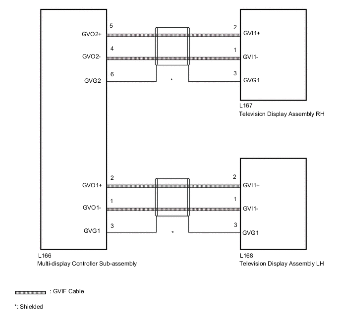
WIRING DIAGRAM
PROCEDURE
-
CHECK HARNESS AND CONNECTOR (GVIF CABLE)
-
Check if the GVIF cable connectors between the multi-display controller sub-assembly and the television display assembly have any connection problems.
OK There are no connection problems. Result Proceed to OK NG
NG 
REPAIR OR REPLACE HARNESS OR CONNECTOR
OK 
-
-
CHECK HARNESS AND CONNECTOR (GVIF CABLE)
-
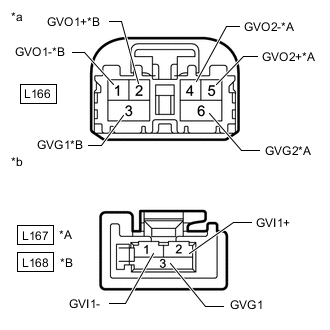
*A for RH *B for LH *a GVIF Cable
(to Multi-display Controller Sub-assembly)
*b GVIF Cable
(to Television Display Assembly)
Disconnect the multi-display controller sub-assembly connector.
-
Remove the television display assembly connector.
-
Measure the resistance according to the value(s) in the table below.
Standard Resistance for RH Tester Connection Condition Specified Condition L166-4 (GVO2-) - L167-1 (GVI1-) Always Below 1 Ω L166-5 (GVO2+) - L167-2 (GVI1+) Always Below 1 Ω L166-6 (GVG2) - L167-3 (GVG1) Always Below 1 Ω L166-4 (GVO2-) - Body ground Always 10 kΩ or higher L166-5 (GVO2+) - Body ground Always 10 kΩ or higher L166-6 (GVG2) - Body ground Always 10 kΩ or higher for LH Tester Connection Condition Specified Condition L166-1 (GVO1-) - L168-1 (GVI1-) Always Below 1 Ω L166-2 (GVO1+) - L168-2 (GVI1+) Always Below 1 Ω L166-3 (GVG1) - L168-3 (GVG1) Always Below 1 Ω L166-1 (GVO1-) - Body ground Always 10 kΩ or higher L166-2 (GVO1+) - Body ground Always 10 kΩ or higher L166-3 (GVG1) - Body ground Always 10 kΩ or higher Result Proceed to OK NG OK There are no connection problems.
OK
PROCEED TO NEXT SUSPECTED AREA SHOWN IN PROBLEM SYMPTOMS TABLE Click here
NG
REPLACE HARNESS OR CONNECTOR (GVIF CABLE)
-