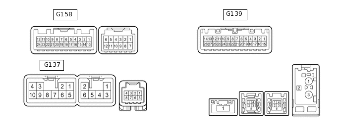
REAR VIEW MONITOR SYSTEM(for Navigation Receiver Type) TERMINALS OF ECU
NAVIGATION RECEIVER ASSEMBLY
Terminal No. (Symbol)
Wiring Color
Terminal Description
Condition
Specified Condition
G137-3 (ACC1) - G137-7 (GND1)
GR - BR
Power source (ACC)
Ignition switch off
Below 1 V
Ignition switch ACC
10 to 16 V
G137-4 (+B1) - G137-7 (GND1)
SB - BR
Power source (+B)
Always
10 to 16 V
G137-7 (GND1) - Body ground
BR - Body ground
Ground
Always
Below 1 Ω
G139-1 (IG) - G137-7 (GND1)
Y - BR
Power source (IG)
Ignition switch off
Below 1 V
Ignition switch ON
10 to 16 V
G139-2 (REV) - G137-7 (GND1)
BE - BR
Reverse signal
See "Vehicle Signal Check Mode" in Operation Check
-
G158-11 (CA+) - G158-23 (CGND)
B - Shielded
Power source
Ignition switch ON
5.5 to 7.05 V
G158-12 (V+) - G158-23 (CGND)
W - Shielded
Video signal
Ignition switch ON, camera lens not covered, displaying an image
Pulse generation
(See waveform 1)
Ignition switch ON, camera lens covered, blacking out the screen
Pulse generation
(See waveform 2)
G158-23 (CGND) - Body ground
Shielded - Body ground
Shielded ground
Always
Below 1 V
G158-24 (V-) - G158-23 (CGND)
R - Shielded
Ground
Always
Below 1 V
-
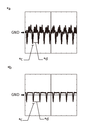
*a
Waveform 1
*b
Waveform 2
*c
Synchronized Signal
*d
Video Waveform
Reference (Oscilloscope waveform):
Waveform 1
Item
Content
Terminal No. (Symbol)
G158-12 (V+) - G158-23 (CGND)
Tool Setting
200 mV/DIV., 50 μsec./DIV.
Condition
Ignition switch ON, camera lens not covered, displaying an image
Waveform 2
Item
Content
Terminal No. (Symbol)
G158-12 (V+) - G158-23 (CGND)
Tool Setting
200 mV/DIV., 50 μsec./DIV.
Condition
Ignition switch ON, camera lens covered, blacking out the screen
Tip:The video waveform changes according to the image sent by the rear television camera assembly.
-