RADIATOR INSTALLATION
PROCEDURE
INSTALL FAN SHROUD
Install the fan shroud with the 3 bolts.
5.5 N*m
56 kgf*cm
49 in.*lbf
INSTALL INTERCOOLER ASSEMBLY
INSTALL LOWER RADIATOR SUPPORT
INSTALL OIL COOLER TUBE SUB-ASSEMBLY (for Automatic Transaxle)
-
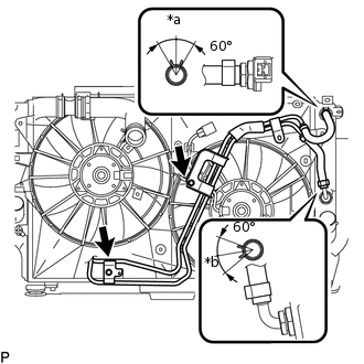
*a
Top
*b
RH Side
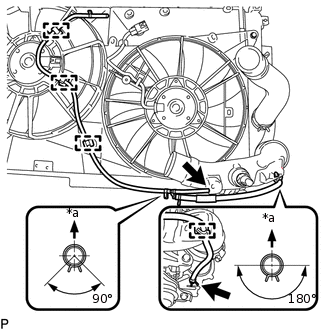
Connect the 2 hoses of the oil cooler hose tube sub-assembly to the radiator assembly and slide the 2 clips to secure the hose.
Tip:Position the clips as illustrated.
Install the oil cooler tube sub-assembly with the 2 bolt.
5.5 N*m
56 kgf*cm
49 in.*lbf
-
INSTALL NO. 2 RADIATOR HOSE
Install the No. 2 radiator hose to the radiator assembly and slide the clamp to secure the hose.
Tip: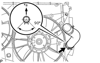
*a
Top
Position the clamp as illustrated.
INSTALL RADIATOR HOSE SUB-ASSEMBLY
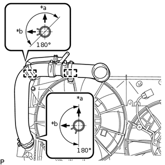
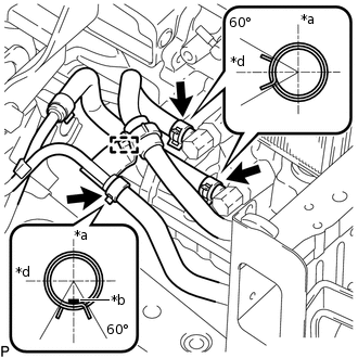
*a
Top
*b
LH Side
Install the radiator hose sub-assembly to the radiator assembly, and slide the 2 clamps to secure the hose.
Tip:Position the clamps as illustrated.
Attach the 2 clamps to the fan shroud.
INSTALL NO. 2 AIR TUBE
Install the No. 2 air tube to the intercooler assembly with the bolt.
Note:Before installation, remove any oil residue from the inside of the No. 2 air tube and intercooler assembly.
31 N*m
316 kgf*cm
23 ft.*lbf
-
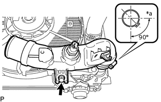
*a
LH Side
Tighten the hose clamp.
6.5 N*m
66 kgf*cm
58 in.*lbf
Tip:Position the clamp as illustrated.
INSTALL NO. 2 VACUUM TRANSMITTING HOSE ASSEMBLY
-
*a
Top
Attach the 4 clamps to the fan shroud and No. 2 air tube.
Install the No. 2 vacuum transmitting hose assembly to the intercooler assembly and No. 2 air hose and 2 clips to secure the hose.
Tip:Position the clips as illustrated.
-
INSTALL COOLER CONDENSER ASSEMBLY
Install the cooler condenser assembly.
INSTALL NO. 2 RADIATOR SUPPORT
Install the 2 No. 2 radiator supports with the 4 bolts.
5.5 N*m
56 kgf*cm
49 in.*lbf
INSTALL RADIATOR ASSEMBLY
Install the 2 cushions.
Insert the radiator assembly.
-
*a
Top
*b
Paint Mark
*c
Front Side of Vehicle
for Automatic Transaxle
Connect the 3 oil cooler hoses to the automatic transaxle, and slide the 3 clips to secure the hose.
Tip:Position the clips as illustrated.
Attach the clamp to the oil cooler tube sub-assembly.
INSTALL NO. 3 AIR HOSE
INSTALL INTERCOOLER AIR HOSE
Note:Before installation, remove any oil residue from the inside of the intercooler air hose.
-
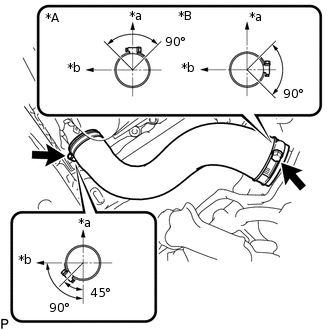
*A
for Manual Transaxle
*B
for Automatic Transaxle
*a
Top
*b
LH Side
Install the intercooler air hose to the No. 1 air tube and intercooler assembly and tighten the 2 hose clamps.
6.5 N*m
66 kgf*cm
58 in.*lbf
Tip:Position the hose clamps as illustrated.
-
CONNECT NO. 2 RADIATOR HOSE
CONNECT RADIATOR HOSE SUB-ASSEMBLY
INSTALL UPPER RADIATOR SUPPORT
Install the upper radiator support with the 4 bolts.
31 N*m
316 kgf*cm
23 ft.*lbf
INSTALL HOOD LOCK ASSEMBLY
for LHD:
for RHD:
CONNECT WIRE HARNESS
w/ Towing Package:
Connect the 3 connectors to the cooling fan ECU and intake air temperature sensor.
Attach the 11 clamps to the fan shroud.
w/o Towing Package:
Connect the 4 connectors to the fan motors, hood courtesy switch and intake air temperature sensor.
Attach the 13 clamps to the fan shroud.
CONNECT NO. 1 WATER BY-PASS HOSE
Connect the No. 1 water by-pass hose clamp bracket to the upper radiator support with the 2 bolts.
5.0 N*m
51 kgf*cm
44 in.*lbf
Attach the hose clamp to the upper radiator support.
Connect the No. 1 water by-pass hose to the radiator reservoir assembly, and radiator hose sub-assembly and slide the 2 clamps to secure the hose.
INSTALL NO. 1 RADIATOR SUPPORT
Install the 2 radiator support cushions.
Install the 2 No. 1 radiator supports with the 2 bolts.
19 N*m
194 kgf*cm
14 ft.*lbf
CONNECT NO. 2 VACUUM TRANSMITTING HOSE ASSEMBLY
Connect the No. 2 vacuum transmitting hose assembly, and slide the clip secure the hose.
INSTALL REAR RADIATOR SIDE AIR GUIDE PLATE LH
Install the rear radiator side air guide plate LH with the 2 clips.
INSTALL FRONT RADIATOR SIDE AIR GUIDE PLATE LH
Install the front radiator side air guide plate LH and attach the 3 claws.
INSTALL REAR RADIATOR SIDE AIR GUIDE PLATE RH
Install the rear radiator side air guide plate RH with the 2 clips.
INSTALL FRONT RADIATOR SIDE AIR GUIDE PLATE RH
Install the front radiator side air guide plate RH and attach the 3 claws.
CONNECT LIQUID TUBE SUB-ASSEMBLY
Remove the attached vinyl tape from the liquid tube sub-assembly and connecting part of the cooler condenser assembly.
Sufficiently apply compressor oil to a new O-ring and the fitting surface of the tube joint.
Compressor Oil
ND-OIL 8 or equivalent
Connect the liquid tube sub-assembly to the cooler condenser assembly with the bolt.
5.4 N*m
55 kgf*cm
48 in.*lbf
CONNECT DISCHARGE HOSE SUB-ASSEMBLY
Remove the attached vinyl tape from the discharge hose sub-assembly and connecting part of the cooler condenser assembly.
Sufficiently apply compressor oil to a new O-ring and the fitting surface of the hose joint.
Compressor Oil
ND-OIL 8 or equivalent
Connect the discharge hose sub-assembly to the cooler condenser assembly with the bolt.
5.4 N*m
55 kgf*cm
48 in.*lbf
INSTALL FRONT BUMPER REINFORCEMENT
CONNECT AMBIENT TEMPERATURE SENSOR ASSEMBLY
Attach the clamp to connect the ambient thermistor assembly.
INSTALL LOWER RADIATOR AIR GUIDE PLATE
Install the lower radiator guide plate and attach the 3 claws.
INSTALL UPPER RADIATOR AIR GUIDE PLATE
Install the upper radiator air guide plate with 6 clips.
INSTALL FRONT BUMPER UPPER REINFORCEMENT SUB-ASSEMBLY
Install the front bumper upper reinforcement sub-assembly with the 2 bolts.
INSTALL FRONT BUMPER CENTER STAY SUB-ASSEMBLY
Install the front bumper center stay sub-assembly with the 2 bolts and clip.
INSTALL LOW PITCHED HORN ASSEMBLY
INSTALL HIGH PITCHED HORN ASSEMBLY
INSTALL BATTERY BRACKET REINFORCEMENT
INSTALL FRONT BATTERY BRACKET
INSTALL BATTERY TRAY
INSTALL BATTERY
INSTALL BATTERY INSULATOR
INSTALL BATTERY CLAMP SUB-ASSEMBLY
INSTALL FRONT LOWER BUMPER ABSORBER
Install the front lower bumper absorber with the 4 screws.
INSTALL HEADLIGHT ASSEMBLY
for Halogen Headlight:
for LED Headlight:
INSTALL FRONT BUMPER COVER
CONNECT CABLE TO POSITIVE BATTERY TERMINAL
CONNECT CABLE TO NEGATIVE BATTERY TERMINAL
Note:When disconnecting the cable, some systems need to be initialized after the cable is reconnected.
ADD ENGINE COOLANT
CHARGE REFRIGERANT
WARM UP ENGINE
INSPECT FOR REFRIGERANT LEAK
ADJUSTMENT AUTOMATIC TRANSAXLE FLUID (for Automatic Transaxle)
INSPECT FOR COOLANT LEAK
INSTALL NO. 1 ENGINE COVER
INSTALL NO. 1 ENGINE UNDER COVER