MANUAL TRANSAXLE SYSTEM, Diagnostic DTC:P050031
| DTC Code | DTC Name |
|---|---|
| P050031 | Vehicle Speed Sensor "A" No Signal |
DESCRIPTION
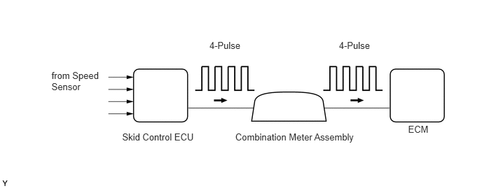
Vehicles, which are equipped with ABS (Anti-lock Brake System), detect the vehicle speed using the skid control ECU (brake actuator assembly) and speed sensors. Each speed sensor monitors the wheel rotation speed and sends a signal to the skid control ECU. The skid control ECU converts the wheel speed signals into a 4-pulse signal and transmits it to the ECM via the combination meter assembly. The ECM determines the vehicle speed based on the frequency of the pulse signal.
Various systems use the vehicle speed signal distributed from the combination meter assembly. Check all the components possibly related to the speed signal.
A voltage of 12 V or 5 V is output from each ECU and then input to the combination meter assembly. The signal is changed to a pulse signal at the transistor in the combination meter assembly. Each ECU controls the respective system based on the pulse signal.
If a short occurs in any of the ECUs or in the wire harness connected to an ECU, all systems using the speed signal will not operate normally.
DTC No. |
Detection Item |
DTC Detection Condition |
Trouble Area |
MIL |
Memory |
Note |
|---|---|---|---|---|---|---|
P050031 |
Vehicle Speed Sensor "A" No Signal |
1. Diagnosis Condition 2. Malfunction Status 3. Malfunction Time 4. Other
|
|
Does not come on |
DTC stored |
SAE Code: P0500 |
MONITOR DESCRIPTION
If there is no speed signal from the combination meter assembly even though the ECM determines that the vehicle is being driven, the ECM interprets this as a malfunction in the speed signal circuit. The ECM then illuminates the MIL and stores this DTC.
WIRING DIAGRAM
Refer to SFI system DTC P050031.
CAUTION / NOTICE / HINT
Read freeze frame data using the GTS. The ECM records vehicle and driving condition information as freeze frame data the moment a DTC is stored. When troubleshooting, freeze frame data can help determine if the vehicle was moving or stationary, if the engine was warmed up or not, if the air fuel ratio was lean or rich, and other data from the time the malfunction occurred.
After performing repair, clear the DTCs and perform the following procedure to check that DTCs are not output.
-
Turn the ignition switch to ON and wait for 3 seconds or more.
Drive the vehicle for 6 seconds or more.
Turn the ignition switch off.
Perform steps (a) and (b) again.
Check for DTCs again.
PROCEDURE
CHECK DTC OUTPUT (SFI SYSTEM)
Check for SFI system DTCs.
Powertrain > Engine > Trouble Codes
Result
Result
Proceed to
DTCs are not output
A
DTCs are output
B