STARTER(w/ Stop And Start System) REASSEMBLY
PROCEDURE
INSTALL STARTER CENTER BEARING CLUTCH SUB-ASSEMBLY
-
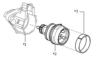
*1
Starter Drive Housing Assembly
*2
Starter Center Bearing Clutch Sub-assembly
*3
Collar Space
Install the starter center bearing clutch sub-assembly into the starter drive housing assembly.
-
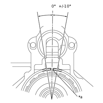
*a
Collar Space End Gap
Install the collar space into the starter center bearing clutch sub-assembly.
Note:Make sure that the collar space end gap is within +/-10° from the center of the starter drive housing assembly.
-
INSTALL PLANETARY GEAR AND WASHER
-
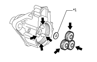
*1
Washer

High-temperature Grease
Apply high-temperature grease to the planetary gears and pins of the planetary shaft as shown in the illustration.
Install the washer and 3 planetary gears.
-
INSTALL STARTER WITH CLUTCH ARMATURE ASSEMBLY
-
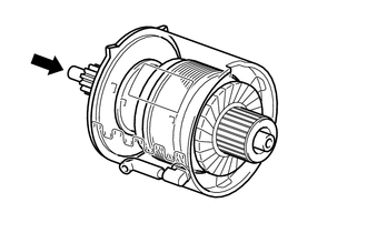
Install the starter with clutch armature assembly onto the starter yoke assembly.
Note:When installing the starter with clutch armature assembly, be sure to hold the front of the armature to prevent the armature from coming off the clutch.
-
INSTALL STARTER BRUSH HOLDER ASSEMBLY
-
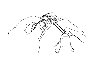
Using a screwdriver, hold each brush spring back and install the 4 brushes into the starter brush holder assembly.
Install the starter brush holder assembly to the starter with clutch armature assembly.
-
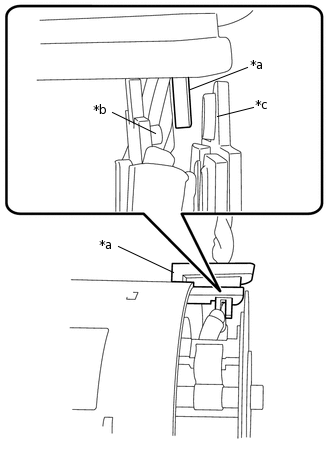
*a
Grommet
*b
Ground Plate (Negative Side)
*c
Plate (Positive Side)
Insert the grommet between the plate and ground plate.
Note:Make sure that the grommet is properly inserted into the starter yoke assembly.
-
INSTALL STARTER COMMUTATOR END FRAME ASSEMBLY
Engage the clamp of the starter brush holder assembly with the starter commutator end frame assembly.
-
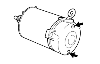
Install the starter commutator end frame assembly with the 2 screws.
1.5 N*m
15 kgf*cm
13 in.*lbf
-
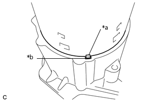
*a
Protrusion
*b
Cutout
Install the starter yoke assembly, starter with clutch armature assembly and starter commutator end frame assembly to the starter drive housing assembly.
Note:Align the protrusion of the starter yoke assembly with the cutout of the starter drive housing assembly.
-
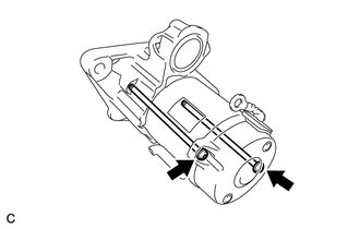
Using a T25 "TORX" socket wrench, install the starter yoke assembly with the 2 through bolts.
6.0 N*m
61 kgf*cm
53 in.*lbf
-
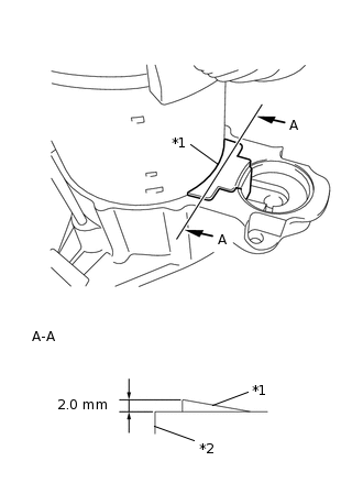
*1
Rubber Seal
*2
Starter Drive Housing Assembly
Install the rubber seal to the starter drive housing assembly.
Note:Make sure that the rubber seal does not protrude more than 2.0 mm (0.0787 in.) from the outer surface of the starter drive housing assembly.
INSTALL REPAIR SERVICE STARTER KIT
-
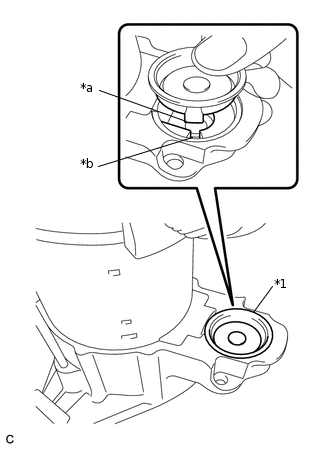
*1
Cover
*a
Protrusion
*b
Cutout
Align the protrusion of the cover with the cutout of the starter drive housing assembly and install the cover.
Note:Make sure that the cover does not overlap the rubber seal.
-
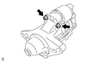
Install the repair service starter kit with the 2 nuts.
7.5 N*m
76 kgf*cm
66 in.*lbf
-
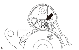
Connect the 2 lead wires to terminal C with the nut.
10 N*m
102 kgf*cm
7 ft.*lbf
-