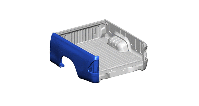
DECK(for Smart Cab) ASSEMBLY REPLACEMENT
Tech Tips
-
Use the same procedure for the RH and LH.
-
The procedure listed below is for the LH.
-
The bold lines in the illustration indicate the removal and installation area.
-
The numbers in the illustration indicate the number of welding points.
-
Measure the dimensions of each part according to the body dimension diagram. (See the body dimensions)
-
REMOVAL
Symbol Meaning 
Cut with Disc Sander etc.
-
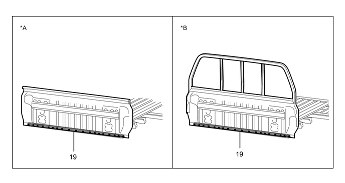
DECK SIDE PANEL
-
REMOVE DECK SIDE PANEL


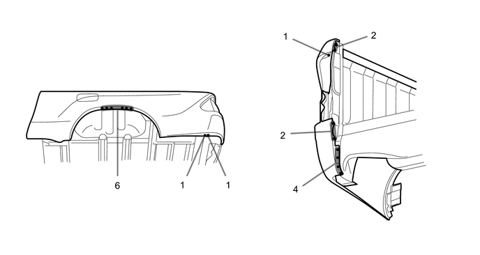

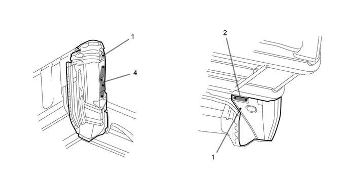
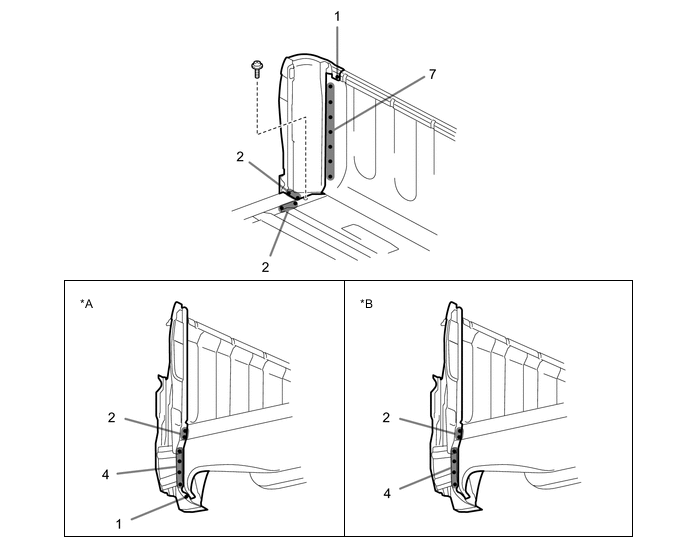
*A w/o Rear Bumper *B w/ Rear Bumper 
-
-
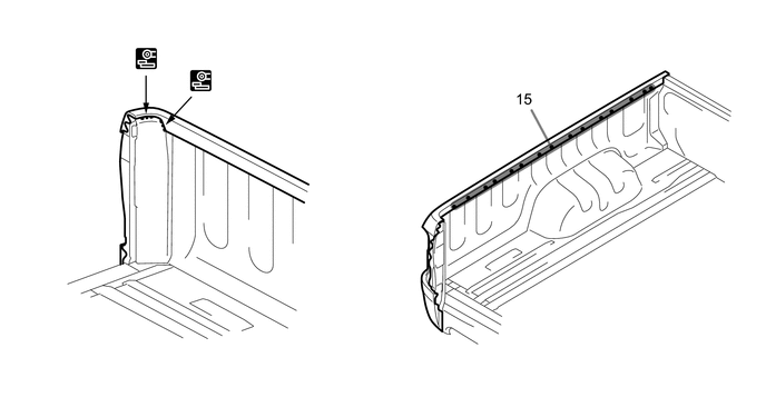
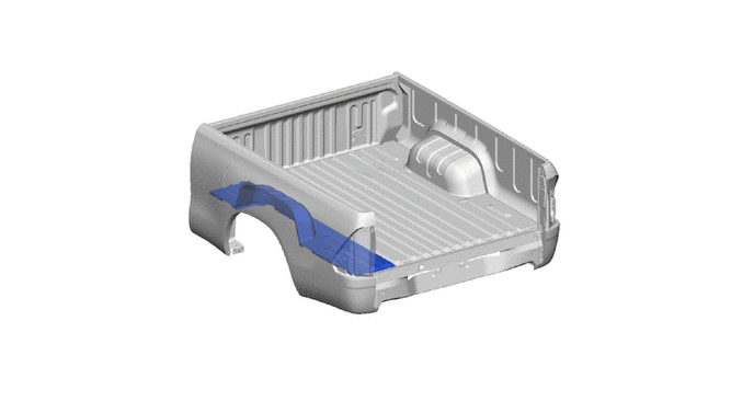
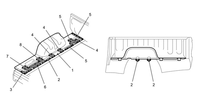
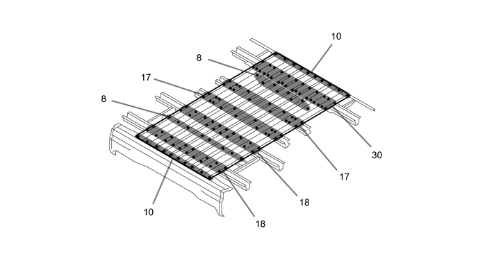
DECK SIDE FLOOR PANEL
-
REMOVE DECK SIDE FLOOR PANEL
-
-
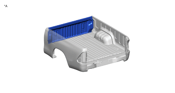
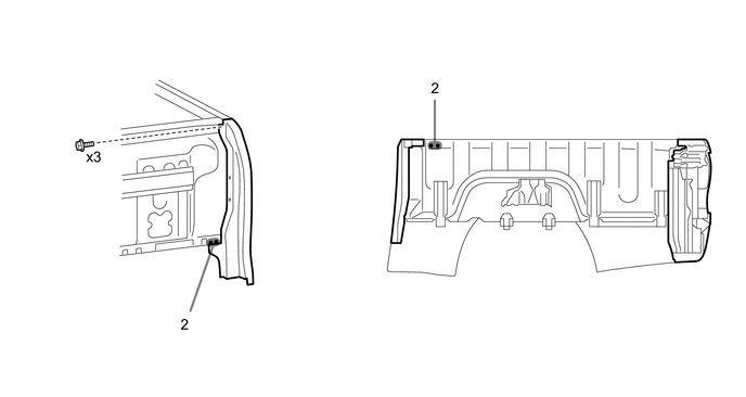
HEADER PANEL
*A w/o Deck Guard Frame - - 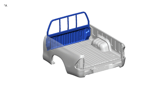
*A w/ Deck Guard Frame - -
-
REMOVE HEADER PANEL

*A w/o Deck Guard Frame *B w/ Deck Guard Frame
-
-
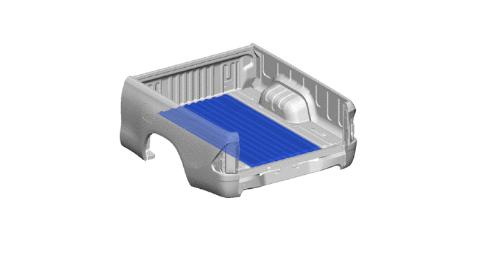
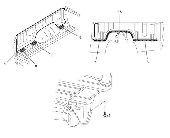
DECK FLOOR PANEL
-
REMOVE DECK FLOOR PANEL
-
-
-
INSTALLATION
Symbol Meaning 
Fillet Weld
-
DECK FLOOR PANEL
-
INSTALL DECK FLOOR PANEL

-
-
HEADER PANEL
*A w/o Deck Guard Frame - -
*A w/ Deck Guard Frame - -
-
REMOVE HEADER PANEL
*A w/o Deck Guard Frame *B w/ Deck Guard Frame
-
-
DECK SIDE FLOOR PANEL
-
INSTALL DECK SIDE FLOOR PANEL

-
-
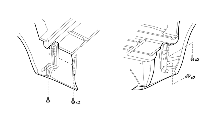
DECK SIDE PANEL
-
INSTALL DECK SIDE PANEL

*A w/o Rear Bumper *B w/ Rear Bumper 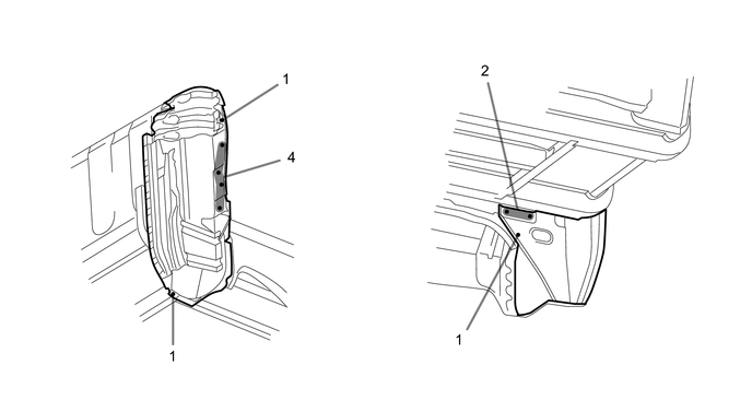

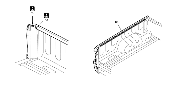
*a 10 mm (0.39 in.) *b 5.5 mm (0.22 in.) 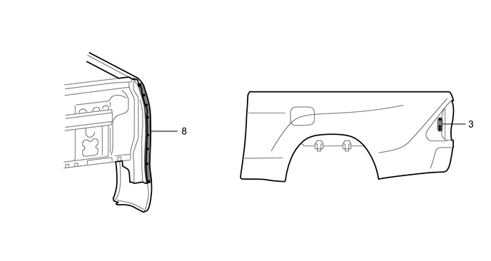
-
-