SFI SYSTEM PRECAUTION
-
INITIALIZATION
Note
-
Perform REGISTRATION (VIN registration) when replacing the ECM Click here.
-
Perform initialization (throttle position) after replacing the throttle body assembly or cleaning any throttle body components Click here.
-
Perform initialization (throttle position) after reconnecting the auxiliary battery cable or replacing the ECM Click here.
-
-
PRECAUTIONS FOR INSPECTING HYBRID CONTROL SYSTEM
-
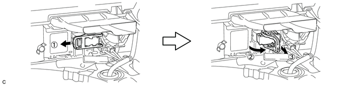
Before inspecting the high-voltage system or disconnecting the low voltage connector of the inverter with converter assembly, take safety precautions such as wearing insulated gloves and removing the service plug grip to prevent electrical shocks. After removing the service plug grip, put it in your pocket to prevent other technicians from accidentally reconnecting it while you are working on the high-voltage system.
Note
-
After turning power switch off, waiting time may be required before disconnecting the cable from the negative (-) auxiliary battery terminal. Therefore, make sure to read the disconnecting the cable from the negative (-) auxiliary battery terminal notices before proceeding with work Click here.
-
After removing the service plug grip, turning the power switch on (READY) may cause a malfunction. Do not turn the power switch on (READY) unless instructed by the repair manual.
-
-
After disconnecting the service plug grip, wait for at least 10 minutes before touching any of the high-voltage connectors or terminals.
Tech Tips
Waiting for at least 10 minutes is required to discharge the high-voltage capacitor inside the inverter with converter assembly.
-
-
NOTICE FOR HYBRID CONTROL SYSTEM ACTIVATION
-
When the warning light is illuminated, or the auxiliary battery has been disconnected and reconnected, attempting to turn the power switch on (READY) may not start the system (the system may not enter the READY-on state) on the first attempt. If so, turn the power switch off and reattempt to start the hybrid system.
-
-
FOR USING GTS
CAUTION:
Observe the following items for safety reasons:
-
Before using the GTS, read the instruction manual.
-
Prevent the GTS cable from being caught on the pedals, shift lever or steering wheel when driving with the GTS connected to the vehicle.
-
When driving the vehicle for testing purposes using the GTS, 2 persons are required. One is for driving the vehicle, and the other operates the GTS.
-
-
DISCONNECTING AND RECONNECTING NEGATIVE AUXILIARY BATTERY CABLE
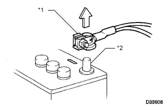
Text in Illustration *1 Cable *2 Negative (-) Auxiliary Battery Terminal
-
Before performing work on electronic components, disconnect the cable from the negative (-) auxiliary battery terminal to prevent damage to the electrical system or electrical components.
-
Before disconnecting and reconnecting the auxiliary battery cable, turn the power switch off and the headlight switch off. Then loosen the terminal nut completely. Do not damage the cable or terminal.
-
When the auxiliary battery cable is disconnected, the clock and radio settings and stored DTCs are cleared. Therefore, before disconnecting the auxiliary battery cable, make a note of them.
Note
-
After turning power switch off, waiting time may be required before disconnecting the cable from the negative (-) auxiliary battery terminal. Therefore, make sure to read the disconnecting the cable from the negative (-) auxiliary battery terminal notices before proceeding with work Click here.
-
When disconnecting the cable from the negative (-) auxiliary battery terminal, initialize the following systems after the cable is reconnected.
System Name See Procedure Intelligent Parking Assist System Power Door Lock Control System -
-
-
PRECAUTION WHEN REPLACING POWER MANAGEMENT CONTROL ECU AND ECM
HV battery learning values are stored in the power management control ECU and ECM to illuminate the hybrid battery indicator light in the combination meter assembly. When either of these ECUs is replaced, the new ECU receives the HV battery learning value data from the other ECU and updates the information.
Note
-
Do not replace the power management control ECU and ECM at the same time as it clears the HV battery learning values. However, if it is necessary to replace both ECUs at the same time, replace them by following the procedure below.
-
Do not replace the power management control ECU or ECM with used ones from other vehicles.
-
Procedure when replacing both power management control ECU and ECM:
-
Disconnect the cable from the negative (-) auxiliary battery terminal.
-
Replace either of the ECUs.
-
Connect the cable to the negative (-) auxiliary battery terminal.
-
Turn the power switch on (READY) and wait for 5 minutes or more.
-
Turn the power switch off and disconnect the cable from the negative (-) auxiliary battery terminal.
-
Replace the other ECU.
-
Connect the cable to the negative (-) auxiliary battery terminal.
-
Check that the power switch can be turned on (READY).
Tech Tips
If the power management control ECU and ECM are replaced at the same time without following the above procedure, replace either of the ECUs with its original one and then replace it again by following the above procedure. If the correct procedure is not followed, perform the procedure again from the beginning.
-
-
-
COOLING FAN SYSTEM
Note
-
When the power switch is turned off and the engine temperature is high, the engine water pump assembly and cooling fans may operate for a maximum of 3 minutes depending on the auxiliary battery voltage.
-
After turning the power switch off, keep hands and objects away from the fans when they are operating.
Tech Tips
-
If all of the following are met for a certain period of time during a few minutes immediately before the power switch is turned off, the cooling fans will continue to operate for a maximum of 3 minutes after the engine is stopped. This is performed to ensure restartability.
-
The GTS indicates a very high coolant temperature.
-
The GTS indicates a high outside air temperature.
-