STOP AND START SYSTEM(for 2WW) Engine Hood Courtesy Switch Circuit
| DTC Code | DTC Name |
|---|---|
| Engine Hood Courtesy Switch Circuit |
DESCRIPTION
The engine stop and start ECU detects open/close of the engine hood based on a signal received from the engine hood courtesy switch that is built into the hood lock assembly.
The engine stop and start ECU prohibits starting of the engine by stop and start control and stalls the engine if the clutch pedal is depressed with the engine hood open while the engine is stopped by stop and start control.
The engine stop and start ECU permits starting of the engine by stop and start control if the engine hood is opened with the clutch pedal depressed while the engine is stopped by stop and start control.
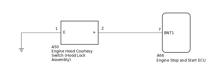
WIRING DIAGRAM
PROCEDURE
READ VALUE USING GTS (HOOD COURTESY SWITCH)
Note:Before performing this step, check that the engine hood can be opened by pulling the hood lock control cable.
Connect the GTS to the DLC3.
Turn the ignition switch to ON.
Turn the GTS on.
Enter the following menus: Powertrain / Stop and Start / Data List / Hood Courtesy Switch.
Powertrain > Stop and Start > Data List
Tester Display
Hood Courtesy Switch
Read the value displayed on the GTS when the engine hood is opened and closed.
OK
Tester Display
Condition
Normal Condition
Hood Courtesy Switch
Engine hood is closed
ON
Engine hood is open
OFF
Result
Proceed to
OK
NG
INSPECT ENGINE HOOD COURTESY SWITCH (HOOD LOCK ASSEMBLY)
Inspect the engine hood courtesy switch (hood lock assembly).
Result
Proceed to
OK
NG
CHECK HARNESS AND CONNECTOR (ENGINE HOOD COURTESY SWITCH (HOOD LOCK ASSEMBLY) - BODY GROUND)
Disconnect the A50 engine hood courtesy switch (hood lock assembly) connector.
Measure the resistance according to the value(s) in the table below.
Standard Resistance
Tester Connection
Condition
Specified Condition
A50-1 (E) - Body ground
Always
Below 1 Ω
Result
Proceed to
OK
NG
NG REPAIR OR REPLACE HARNESS OR CONNECTOR
CHECK HARNESS AND CONNECTOR (ENGINE STOP AND START ECU - ENGINE HOOD COURTESY SWITCH (HOOD LOCK ASSEMBLY))
Disconnect the A66 engine stop and start ECU connector.
Disconnect the A50 engine hood courtesy switch (hood lock assembly) connector.
Measure the resistance according to the value(s) in the table below.
Standard Resistance
Tester Connection
Condition
Specified Condition
A66-7 (BNT1) - A50-2 (+)
Always
Below 1 Ω
A66-7 (BNT1) - Body ground
Always
10 kΩ or higher
A50-2 (+) - Body ground
Always
10 kΩ or higher
Result
Proceed to
OK
NG
NG REPAIR OR REPLACE HARNESS OR CONNECTOR