OIL PUMP (w/ Dual VVT-i) INSPECTION
-
REMOVE OIL PUMP ROTOR SET
-
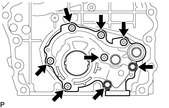
Remove the 2 bolts, 6 screws and oil pump cover from the timing chain or belt cover sub-assembly.
-
Remove the oil pump rotor set from the timing chain or belt cover sub-assembly.
-
-
INSPECT OIL PUMP RELIEF VALVE
-
Coat the oil pump relief valve with engine oil and drop it into the oil pump relief valve hole.
-
Check that the oil pump relief valve falls in smoothly by its own weight. If it does not, replace the oil pump relief valve. If necessary, replace the timing chain or belt cover sub-assembly.
-
-
INSPECT OIL PUMP ROTOR SET
-
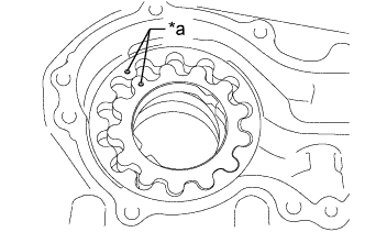
Text in Illustration *a Alignment Mark Install the oil pump rotor set to the oil pump body with the alignment marks facing outward (oil pump cover side). Check that the oil pump rotor set revolves smoothly.
-
Check the tip clearance.
-
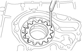
Using a feeler gauge, measure the clearance between the drive rotor and driven rotor tips as shown in the illustration.
Standard tip clearance 0.040 to 0.160 mm (0.00157 to 0.00630 in.) Maximum tip clearance 0.26 mm (0.0102 in.) If the tip clearance is more than the maximum, replace the oil pump rotor set.
-
-
Check the body clearance.
-
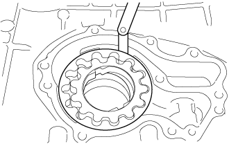
Using a feeler gauge, measure the clearance between the oil pump body and driven rotor as shown in the illustration.
Standard body clearance 0.250 to 0.325 mm (0.00984 to 0.0128 in.) Maximum body clearance 0.425 mm (0.0167 in.) If the body clearance is more than the maximum, replace the timing chain or belt cover sub-assembly.
-
-
Check the side clearance.
-
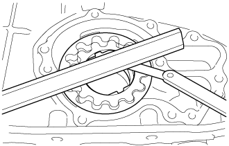
Using a feeler gauge and precision straightedge measure the clearance between the oil pump rotor set and precision straightedge as shown in the illustration.
Standard side clearance 0.03 to 0.07 mm (0.00118 to 0.00276 in.) Maximum side clearance 0.130 mm (0.00512 in.) If the side clearance is more than the maximum, replace the timing chain or belt cover sub-assembly.
-
-
-
INSTALL OIL PUMP ROTOR SET
-
Text in Illustration *a Alignment Mark Coat the oil pump rotor set with engine oil and place it into oil pump body with the alignment marks facing outward (oil pump cover side). Check that the oil pump rotor set revolves smoothly.
-
Install the oil pump cover to the timing chain or belt cover sub-assembly with the 2 bolts and 6 screws.
- Torque:
- for Bolt
- 8.9 N*m { 91 kgf*cm, 79 in.*lbf }
- for Screw
- 10 N*m { 102 kgf*cm, 7 ft.*lbf }
-