METER / GAUGE SYSTEM Tachometer Malfunction
| DTC Code | DTC Name |
|---|---|
| Tachometer Malfunction |
DESCRIPTION
In this circuit, the combination meter assembly receives engine speed signals from the ECM via the CAN communication system. The combination meter assembly displays the engine speed calculated based on the data received from the ECM.
WIRING DIAGRAM
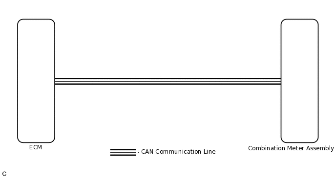
CAUTION / NOTICE / HINT
When it is necessary to replace the combination meter assembly, be sure to replace it with a new one.
PROCEDURE
CHECK CAN COMMUNICATION SYSTEM
Check if CAN communication DTCs are output.
Result
Result
Proceed to
CAN communication DTCs are not output.
A
CAN communication DTCs are output.
B
PERFORM ACTIVE TEST USING GTS (TachoMeter Operation)
Connect the GTS to the DLC3.
Turn the ignition switch to ON.
Turn the GTS on.
Enter the following menus: Body Electrical / Combination Meter / Active Test.
Perform the Active Test according to the display on the GTS.
Body Electrical > Combination Meter > Active Test
Tester Display
Measurement Item
Control Range
Diagnostic Note
TachoMeter Operation
Tachometer
OFF, 0, 1000, 2000, 3000, 4000, 5000, 6000, 7000
-
Body Electrical > Combination Meter > Active Test
Tester Display
TachoMeter Operation
OK
Tachometer indication is normal.
Result
Proceed to
OK
NG
READ VALUE USING GTS (Engine Rpm)
Connect the GTS to the DLC3.
Turn the ignition switch to ON.
Turn the GTS on.
Enter the following menus: Body Electrical / Combination Meter / Data List.
Read the Data List according to the display on the GTS.
Body Electrical > Combination Meter > Data List
Tester Display
Measurement Item
Range
Normal Condition
Diagnostic Note
Engine Rpm
Engine speed
Min.: 0 rpm, Max.: 12750 rpm
Almost the same as actual engine speed
-
Body Electrical > Combination Meter > Data List
Tester Display
Engine Rpm
OK
Engine speed displayed on the GTS is almost the same as the tachometer indication.
Tip:When the data list values and tachometer values match, a signal output malfunction of the ECM or an internal malfunction of the combination meter assembly is suspected.
When the data list values and tachometer values do not match, an internal malfunction of the combination meter assembly is suspected.
Result
Proceed to
OK
NG
CHECK FOR DTC
Check if SFI System DTCs are output.
for 1KR-FE:Click here
for 1PP:Click here
Powertrain > Engine and ECT > Trouble Codes
Result
Result
Proceed to
SFI system DTCs are not output.
A
SFI system DTCs are output.
B
READ VALUE USING GTS (Engine Speed, Engine Rpm)
Connect the GTS to the DLC3.
Turn the ignition switch to ON.
Turn the GTS on.
Enter the following menus:
for 1KR-FE:
for Engine and ECT: Powertrain / Engine and ECT / Data List.
for 1PP:
for Engine: Powertrain / Engine / Data List.
for Combination Meter: Body Electrical / Combination Meter / Data List.
Read the Data List according to the display on the GTS.
Engine and ECT (for 1KR-FE)
Powertrain > Engine and ECT > Data List
Tester Display
Measurement Item
Range
Normal Condition
Diagnostic Note
Engine Speed
Engine speed
Min.: 0 rpm, Max.: 16383 rpm
790 to 890 rpm: Idling
When the crankshaft position sensor is malfunctioning, "Engine Speed" is approximately 0 rpm or varies greatly from the actual engine speed.
Powertrain > Engine and ECT > Data List
Tester Display
Engine Speed
Engine (for 1PP)
Powertrain > Engine > Data List
Tester Display
Measurement Item
Range
Reference Value
Engine Regime
Engine speed
Min.: 0 rpm, Max.: 8000 rpm
846 rpm:
Idle (warmed up)
Powertrain > Engine > Data List
Tester Display
Engine Regime
Combination Meter
Body Electrical > Combination Meter > Data List
Tester Display
Measurement Item
Range
Normal Condition
Diagnostic Note
Engine Rpm
Engine speed
Min.: 0 rpm, Max.: 12750 rpm
Almost the same as actual engine speed
-
Body Electrical > Combination Meter > Data List
Tester Display
Engine Rpm
Result
Result
Proceed to
The data list values of the ECUs do not match.
A
The data list values of the ECUs match.
B
Tip:When the data list values of the ECUs match, an internal malfunction of the ECM is suspected.
When the data list values of the ECUs do not match, a signal output malfunction of the ECM or an internal malfunction of the combination meter assembly is suspected.
REPLACE COMBINATION METER ASSEMBLY
Replace the combination meter assembly with a new or known good one.
OK
The operation of the tachometer returns to normal.
Result
Proceed to
OK
NG
OK END