ENGINE UNIT DETAILS CYLINDER HEAD
CONSTRUCTION
The spark plug has been located in the center of the combustion chamber in order to achieve high engine's anti-knocking performance.
The angle of the intake and exhaust valves is narrowed and set at 33.5° to realize a compact cylinder head.
A taper squish combustion chamber is used to achieve high anti-knocking performance and intake efficiency. In addition, excellent engine performance and fuel economy have been realized.
The exhaust port for each cylinder is merged inside the cylinder head sub-assembly to accelerate warm-up of the TWC, thus improving the fuel economy. In addition, at high engine speeds, with the effective cooling of the exhaust gases, the operation range for maintaining stoichiometric air-fuel mixture ratio is widened, thus reducing rich air-fuel mixtures and also improving fuel economy.
By enlarging the merged port diameter of the exhaust port, exhaust gas back-pressure has been reduced, providing greater torque.
The cylinder head bolt employs plastic region tightening bolts.
The routing of the water jacket in the cylinder head sub-assembly is optimized to achieve high cooling performance.
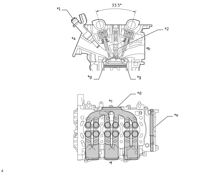
*1
Fuel Injector Assembly
*2
Spark Plug
*a
Intake Port
*b
Exhaust Port
*c
Exhaust Side
*d
Merged Port
*e
EGR Gas Passage
*f
Intake Side
*g
Taper Squish
-
-
A dual injector system is used. By locating a fuel injector assembly at each intake port leading to the intake valves, injection is optimized for enhanced fuel combustion.
Figure 1. Intake Port Image 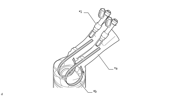
*1
Fuel Injector Assembly
-
-
*a
Intake Port
*b
Tumble Flow