ЗАДАЮЩАЯ ШЕСТЕРНЯ СНЯТИЕ
-
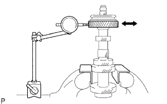
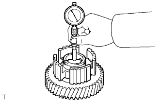
INSPECT COUNTER SHAFT 5TH GEAR RADIAL CLEARANCE
-
Install the 5th gear thrust washer lock ball, the 5th gear thrust washer and the 5th gear to the counter gear.
-
Using a dial indicator, measure the 5th gear radial clearance.
Standard clearance 0.008 to 0.034 mm (0.0003 to 0.0013 in.)
-
If the clearance is not as specified, replace the 5th gear bearing.
-
-
-
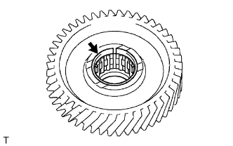
REMOVE COUNTER 5TH GEAR BEARING
-
Remove the 5th gear bearing from the 5th gear.
-
-
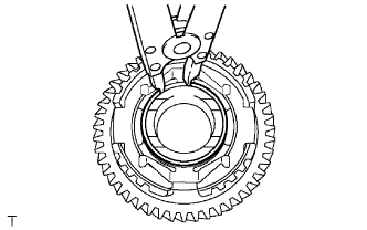
REMOVE NO. 3 TRANSMISSION HUB SLEEVE
-
Using a snap ring expander, remove the snap ring from the 5th gear.
-
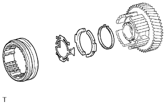
Remove the No. 3 hub sleeve, 2 No. 3 synchromesh shifting keys, key spring (return spring) and key spring (C spring) from the 5th gear.
-
-
INSPECT NO. 3 SYNCHRONIZER RING
-
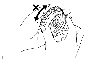
Coat the No. 5 gear spline piece cone with gear oil. Check the braking effect of the No. 3 synchronizer ring. Fit the ring to the shaft cone. Apply pressure to the ring and attempt to turn it in both directions. Check that the ring locks.
-
If the braking effect is insufficient, apply a small amount of fine lapping compound between the No. 3 synchronizer ring and the No. 5 gear spline piece cone. Lightly rub the No. 3 synchronizer ring and No. 5 gear spline piece cone.
Note
Ensure the fine lapping compound is completely washed off after rubbing.
-
-
Check the braking effect of the No. 3 synchronizer ring again.
-
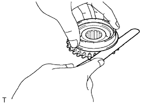
Using a feeler gauge, measure the clearance between the No. 3 synchronizer ring back and the No. 5 gear spline piece cone.
Standard clearance 0.65 to 1.35 mm (0.0256 to 0.0531 in.)
-
If the clearance is not as specified, replace the No. 3 synchronizer ring, and apply a small amount of fine lapping compound on the No. 5 gear spline piece cone.
Note
Ensure the fine lapping compound is completely washed off after rubbing.
-
-
-
INSPECT NO. 3 TRANSMISSION HUB SLEEVE
-
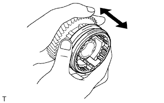
Check the sliding condition between the No. 3 hub sleeve and center shaft 5th gear.
-
Check that the spline gear's edges of the No. 3 hub sleeve are not worn down.
-
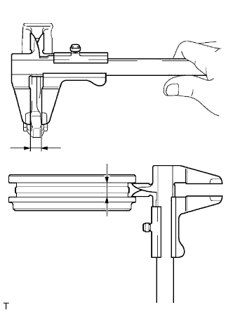
Using a vernier caliper, measure the No. 3 hub sleeve and No. 3 gear shift fork as shown in the illustration.
Standard clearance 0.25 to 0.45 mm (0.0098 to 0.0177 in.)
-
If the clearance is not as specified, replace the No. 3 hub sleeve and No. 3 gear shift fork.
-
-
-
INSPECT COUNTER SHAFT 5TH GEAR
-
Using a cylinder gauge, measure the inside diameter of the 5th gear.
Standard inside diameter 33.015 to 33.040 mm (1.2998 to 1.3008 in.) Maximum inside diameter 33.040 mm (1.3008 in.)
-
If the inside diameter is greater than the maximum, replace the 5th gear.
-
-
-
INSPECT COUNTER GEAR
-
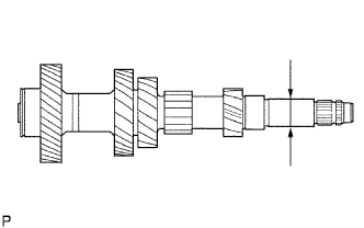
Using a micrometer, measure the outside diameter of the journal surface.
Standard outside diameter 25.984 to 26.000 mm (1.0230 to 1.0236 in.) Minimum outside diameter 25.984 mm (1.0230 in.)
-
If the outside diameter is less than the minimum, replace the counter gear.
-
-
-
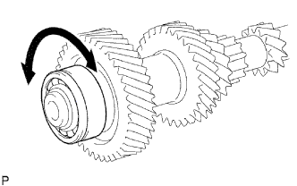
INSPECT COUNTER GEAR FRONT BEARING
-
Make sure the front bearing rotates smoothly.
-
If the bearing does not rotate smoothly, replace the bearing.
-
-
-
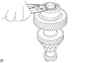
REPLACE COUNTER GEAR FRONT BEARING
-
Using a snap ring expander, remove the No. 2 counter gear front bearing snap ring from the counter gear.
-
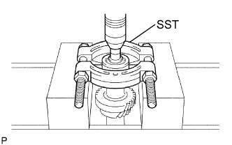
Using SST, a press and 14 mm socket wrench, remove the counter gear front bearing from the counter gear.
- SST
- 09515-10010
-