LIGHTING SYSTEM Headlight Signal Circuit
DESCRIPTION
The headlight leveling ECU assembly detects the status of the low beam headlights.
WIRING DIAGRAM
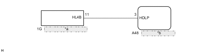
| *a | No. 1 Integration Relay |
| *b | Headlight Leveling ECU Assembly |
CAUTION / NOTICE / HINT
Note
First check that the low beam headlights operate normally.
PROCEDURE
-
READ VALUE USING GTS
-
Connect the GTS to the DLC3.
-
Turn the power switch on (IG).
-
Turn the GTS on.
-
Enter the following menus: Body Electrical / HL Auto Leveling / Data List.
-
Read the display on the GTS.
HL Auto Leveling Tester Display Measurement Item/Range Normal Condition Diagnostic Note Lo Beam St Low beam headlight state/ON or OFF ON: Low beam headlights on
OFF: Low beam headlights off
- OK Normal conditions listed above are displayed.
OK 
PROCEED TO NEXT SUSPECTED AREA SHOWN IN PROBLEM SYMPTOMS TABLE Click here
NG 
-
-
CHECK HARNESS AND CONNECTOR (NO. 1 INTEGRATION RELAY - HEADLIGHT LEVELING ECU ASSEMBLY)
-
Disconnect the A48 headlight leveling ECU assembly connector.
-
Disconnect the 1G No. 1 integration relay connector.
-
Measure the resistance according to the value(s) in the table below.
Standard Resistance Tester Connection Condition Specified Condition A48-3 (HDLP) - 1G-11 (HL4B) Always Below 1Ω A48-3 (HDLP) - Body ground Always 10 kΩ or higher
OK
REPLACE HEADLIGHT LEVELING ECU ASSEMBLY Click here
NG
REPAIR OR REPLACE HARNESS OR CONNECTOR
-