OUTPUT SHAFT INSPECTION

PROCEDURE
-
INSPECT REAR OUTPUT SHAFT BEARING
-
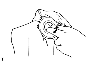
Check the rear output shaft bearing.
Standard Abnormal fitting, interfering, abnormal noise, or looseness should not be found. Tech Tips
If any abnormality is found, replace the rear output shaft bearing with a new one.
-
-
INSPECT OUTPUT SHAFT
-
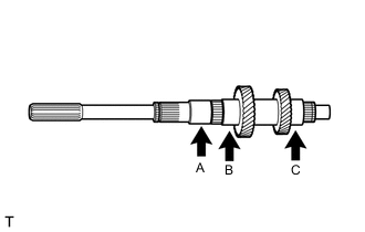
Using a micrometer, measure the outer diameter of each point.
Standard Outer Diameter Part Standard outer diameter mm (in.) Minimum outer diameter mm (in.) A 31.984 to 32.000 (1.25921 to 1.25984) 31.984 (1.25921) B 42.984 to 43.000 (1.69228 to 1.69291) 42.984 (1.69228) C 40.984 to 41.000 (1.61354 to 1.61417) 40.984 (1.61354) Tech Tips
If the outer diameter is less than minimum, replace the output shaft with a new one.
-
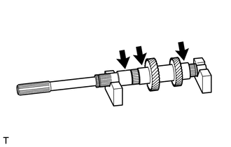
Using V-blocks and a dial indicator, measure the runout of each location as shown in the illustration.
Standard runout 0.03 mm (0.00118 in.) or less Tech Tips
If the runout is outside the specification, replace the output shaft with a new one.
-
-
INSPECT REVERSE GEAR
-
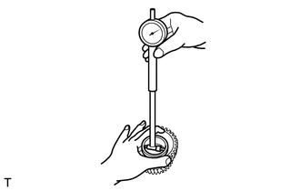
Using a cylinder gauge, measure the inner diameter of the reverse gear.
Standard inside diameter 47.015 to 47.040 mm (1.85098 to 1.85197 in.) Maximum inside diameter 47.040 mm (1.85197 in.) Tech Tips
If the inner diameter exceeds the maximum, replace the reverse gear with a new one.
-
-
INSPECT 1ST GEAR
-
Using a cylinder gauge, measure the inside diameter of the 1st gear.
Standard inside diameter 46.315 to 46.340 mm (1.82343 to 1.82441 in.) Maximum inside diameter 46.340 mm (1.82441 in.) Tech Tips
If the inside diameter exceeds the maximum, replace the 1st gear with a new one.
-
-
INSPECT 2ND GEAR
-
Using a cylinder gauge, measure the inside diameter of the 2nd gear.
Standard inside diameter 49.015 to 49.040 mm (1.92972 to 1.93071 in.) Maximum inside diameter 49.040 mm (1.93071 in.) Tech Tips
If the inside diameter exceeds the maximum, replace the 2nd gear with a new one.
-
-
INSPECT 1ST GEAR BEARING INNER RACE
-
Using a micrometer, measure the outside diameter of the 1st gear bearing inner race.
Standard outer diameter 40.284 to 40.300 mm (1.58598 to 1.58661 in.) Minimum outer diameter 40.284 mm (1.58598 in.) Tech Tips
If the outside diameter is less than minimum, replace the 1st gear bearing inner race with a new one.
-
-
INSPECT NO. 1 TRANSMISSION HUB SLEEVE CLEARANCE
-
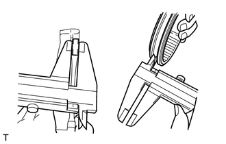
Using a vernier caliper, measure the claw width of the No. 1 gear shift fork.
Standard width 7.9 to 8.0 mm (0.311 to 0.315 in.) Minimum width 7.9 mm (0.311 in.) Tech Tips
If the width is less than the minimum, replace the No. 1 gear shift fork with a new one.
-
Using a vernier caliper, measure the groove of the No. 1 transmission hub sleeve, and then calculate the clearance with the No. 1 gear shift fork.
Standard clearance 0.15 to 0.35 mm (0.00590 to 0.0138 in.) Maximum clearance 0.35 mm (0.0138 in.) Tech Tips
If the clearance exceeds the maximum, replace both the No. 1 gear shift fork and No. 1 transmission hub sleeve with a new ones.
-
-
INSPECT NO. 3 TRANSMISSION HUB SLEEVE CLEARANCE
-
Using a vernier caliper, measure the claw width of the No. 3 gear shift fork.
Standard width 7.9 to 8.0 mm (0.311 to 0.315 in.) Minimum width 7.9 mm (0.311 in.) Tech Tips
If the width is less than the minimum, replace the No. 3 gear shift fork with a new one.
-
Using a vernier caliper, measure the groove of the No. 3 transmission hub sleeve, and then calculate the clearance with the No. 3 gear shift fork.
Standard clearance 0.15 to 0.35 mm (0.00590 to 0.0138 in.) Maximum clearance 0.35 mm (0.0138 in.) Tech Tips
If the clearance exceeds the maximum, replace both the No. 3 gear shift fork and No. 3 transmission hub sleeve with a new ones.
-
-
INSPECT NO. 1 TRANSMISSION HUB SLEEVE
-
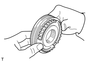
Check that the spline gear edges of the No. 1 transmission hub sleeve are not worn down.
Tech Tips
If it shows any sign of wear, replace the No. 1 transmission hub sleeve with a new one.
-
Install the No. 1 transmission hub sleeve to the No. 1 transmission clutch hub, and then check that it slides smoothly.
Tech Tips
If it does not slide smoothly, replace the No. 1 transmission hub sleeve and No. 1 transmission clutch hub with a new one.
-
-
INSPECT NO. 3 TRANSMISSION HUB SLEEVE
-
Check that the spline gear edges of the No. 3 transmission hub sleeve are not worn down.
Tech Tips
If it shows any sign of wear, replace the No. 3 transmission hub sleeve with a new one.
-
Install the No. 3 transmission hub sleeve to the No. 3 transmission clutch hub, and then check that it slides smoothly.
Tech Tips
If it does not slide smoothly, replace the No. 3 transmission hub sleeve and No. 3 transmission clutch hub with a new one.
-
-
INSPECT NO. 1 SYNCHRONIZER RING SET (for 1st Gear)
-
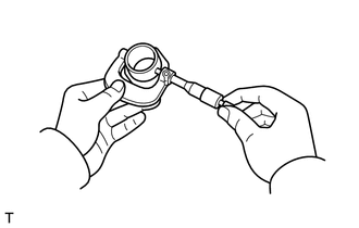
Apply manual transmission gear oil to the taper cone of the 1st gear and No. 1 synchronizer ring set, and then hold the No. 1 synchronizer ring set in position with your hand to measure the clearance between the No. 1 synchronizer ring set and the 1st gear by using a feeler gauge.
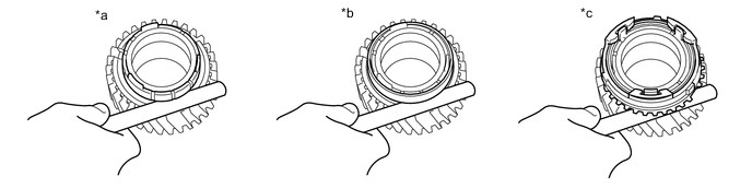
Text in Illustration *a Inner *b Middle *c Outer - - Standard Clearance Location Standard clearance mm ( in.) Inner 0.48 to 1.12 (0.0189 to 0.0441) Middle 0.38 to 1.22 (0.0150 to 0.0480) Outer 0.8 to 1.8 (0.0315 to 0.0709) Note
Check the entire circumference of the gear.
Tech Tips
If the result is not as specified, replace the No. 1 synchronizer ring set with a new one.
-
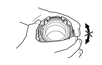
Apply manual transmission gear oil to the taper cone of the 1st gear, and then hold the No. 1 synchronizer ring set in position with your hand to check that it does not slide in the circumferential direction.
Tech Tips
If the No. 1 synchronizer ring set slides, replace the No. 1 synchronizer ring set with a new one.
-
-
INSPECT NO. 1 SYNCHRONIZER RING SET (for 2nd Gear)
-
Apply manual transmission gear oil to the taper cone of the 2nd gear and No. 1 synchronizer ring set, and then hold the No. 1 synchronizer ring set in position with your hand to measure the clearance between the No. 1 synchronizer ring set and the 2nd gear by using a feeler gauge.
Text in Illustration *a Inner *b Middle *c Outer - - Standard Clearance Location Standard clearance mm ( in.) Inner 0.48 to 1.12 (0.0189 to 0.0441) Middle 0.38 to 1.22 (0.0150 to 0.0480) Outer 0.8 to 1.8 (0.0315 to 0.0709) Note
Check the entire circumference of the gear.
Tech Tips
If the result is not as specified, replace the No. 1 synchronizer ring set with a new one.
-
Apply manual transmission gear oil to the taper cone of the 2nd gear, and then hold the No. 1 synchronizer ring in position with your hand to check that it does not slide in the circumferential direction.
Tech Tips
If the No. 1 synchronizer ring set slides, replace the No. 1 synchronizer ring set with a new one.
-