NAVIGATION SYSTEM, Diagnostic DTC:B1532
| DTC Code | DTC Name |
|---|---|
| B1532 | LVDS Signal Malfunction (from Extension Module) |
DESCRIPTION
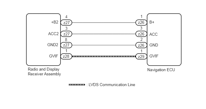
The navigation ECU and the radio and display receiver assembly are connected by the LVDS communication line.
This DTC is stored when an LVDS communication error occurs between the navigation ECU and the radio and display receiver assembly.
DTC Code |
DTC Detection Condition |
Trouble Area |
|---|---|---|
B1532 |
When one of the conditions below is met:
|
|
Even if no fault is present, this DTC may be stored depending on the battery condition or engine start voltage.
The radio and display receiver assembly is the master unit.
WIRING DIAGRAM
CAUTION / NOTICE / HINT
Check that the wire harness is properly installed and does not have any sharp bends, pinching or loose connections (Click here).
PROCEDURE
CHECK HARNESS AND CONNECTOR (NAVIGATION ECU POWER SOURCE)
-
Disconnect the z26 navigation ECU connector.
Measure the resistance according to the value(s) in the table below.
Standard Resistance
Tester Connection
Condition
Specified Condition
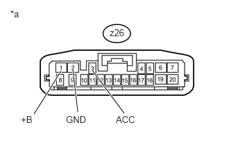
z26-2 (GND) - Body ground
Always
Below 1 Ω
Measure the voltage according to the value(s) in the table below.
Standard Voltage
Tester Connection
Condition
Specified Condition
z26-1 (B+) - z26-2 (GND)
Always
11 to 14 V
z26-3 (ACC) - z26-2 (GND)
Ignition switch ACC
11 to 14 V
Table 1. Text in Illustration *a
Front view of wire harness connector
(to Navigation ECU)
CHECK HARNESS AND CONNECTOR (RADIO AND DISPLAY RECEIVER ASSEMBLY - NAVIGATION ECU)Click here
-
REPLACE HARNESS AND CONNECTOR (LVDS COMMUNICATION LINE)
Replace the harness and connector (LVDS communication line).
Clear the DTCs (Click here).
Check for DTCs and check that no DTCs are output.
OK
No DTCs are output.
END (LVDS COMMUNICATION LINE IS DEFECTIVE)
REPLACE NAVIGATION ECU
Replace the navigation ECU with a known good one (Click here).
Clear the DTCs (Click here).
Check for DTCs and check that no DTCs are output.
OK
No DTCs are output.
END (NAVIGATION ECU IS DEFECTIVE)
CHECK HARNESS AND CONNECTOR (RADIO AND DISPLAY RECEIVER ASSEMBLY - NAVIGATION ECU)
Disconnect the z27 radio and display receiver assembly connector.
Disconnect the z26 navigation ECU connector.
Measure the resistance according to the value(s) in the table below.
Standard Resistance
Tester Connection
Condition
Specified Condition
z27-4 (+B2) - z26-1 (B+)
Always
Below 1 Ω
z27-3 (ACC2) - z26-3 (ACC)
Always
Below 1 Ω
z27-8 (GND2) - z26-2 (GND)
Always
Below 1 Ω
z27-4 (+B2) - Body ground
Always
10 kΩ or higher
z27-3 (ACC2) - Body ground
Always
10 kΩ or higher
z27-8 (GND2) - Body ground
Always
10 kΩ or higher
REPAIR OR REPLACE HARNESS OR CONNECTOR