SIMPLE INTELLIGENT PARKING ASSIST SYSTEM, Diagnostic DTC:C1612
| DTC Code | DTC Name |
|---|---|
| C1612 | IG Voltage is High |
DESCRIPTION
This DTC is stored when the clearance warning ECU assembly judges, as a result of its self check, that the voltage received by terminal IG is not normal.
| DTC No. | Detection Item | DTC Detection Condition | Trouble Area |
|---|---|---|---|
| C1612 | IG Voltage is High | IG voltage is high |
|
-
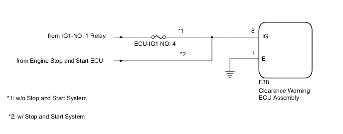
*1: w/ Stop and Start System
WIRING DIAGRAM
CAUTION / NOTICE / HINT
Note
-
Inspect the fuses for circuits related to this system before performing the following procedure.
-
Depending on the parts that are replaced during vehicle inspection or maintenance, performing initialization may be needed. Refer to Calibration.
-
After turning the ignition switch off, waiting time may be required before disconnecting the cable from the negative (-) battery terminal. Therefore make sure to read the disconnecting the cable from the negative (-) battery terminal notices before proceeding with work.
PROCEDURE
-
CHECK DTC OUTPUT
-
Clear the DTCs.
Body Electrical > IPA/ICS/Clearance Sonar > Clear DTCs -
Recheck for DTCs and check if the same DTC is output again.
Body Electrical > IPA/ICS/Clearance Sonar > Trouble CodesOK No DTCs are output. Result Proceed to OK NG
OK 
USE SIMULATION METHOD TO CHECK Click here
NG 
-
-
CHECK HARNESS AND CONNECTOR (CLEARANCE WARNING ECU ASSEMBLY - BODY GROUND)
-
Disconnect the F38 clearance warning ECU assembly connector.
-
Measure the resistance according to the value(s) in the table below.
Standard Resistance Tester Connection Condition Specified Condition F38-1 (E) - Body ground Always Below 1 Ω Result Proceed to OK NG
NG
REPAIR OR REPLACE HARNESS OR CONNECTOR
OK
-
-
CHECK HARNESS AND CONNECTOR (CLEARANCE WARNING ECU ASSEMBLY IG POWER SUPPLY)
-
Disconnect the clearance warning ECU assembly connector.
-
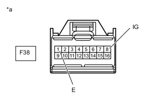
*a Front view of wire harness connector
(to Clearance Warning ECU Assembly)
Measure the voltage according to the value(s) in the table below.
Standard Voltage Tester Connection Condition Specified Condition F38-8 (IG) - F38-1 (E) Ignition switch ON 11 to 14 V*1
9.5 to 14 V*2
-
*1: w/o Stop and Start System
-
*2: w/ Stop and Start System
Result Result Proceed to OK A NG (w/o Stop and Start System) B NG (w/ Stop and Start System) C -
A
REPLACE CLEARANCE WARNING ECU ASSEMBLY Click here
B
REPAIR OR REPLACE HARNESS OR CONNECTOR
C
GO TO STOP AND START SYSTEM Click here
-