ENGINE UNIT
-
CONSTRUCTION
-
By using a PCV system which directly intakes blowby gas from the crankcase to the No. 1 ventilation case, ventilation efficiency has been enhanced and oil deterioration is reduced.
-
A Labyrinth structure is used for the oil mist separator of the No. 1 ventilation case. By enhancing the oil mist collection rate, oil consumption and the buildup of deposits have been decreased.
-
By integrating the PCV valve into the cylinder head, the vacuum hose has been discontinued and the PCV system has been simplified.
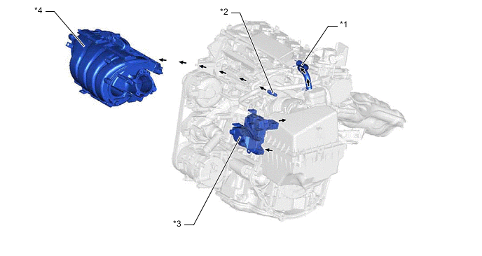
*1 No. 2 Ventilation Hose *2 PCV Valve *3 No. 1 Ventilation Case *4 Intake Manifold Figure 1. PCV Passage Diagram
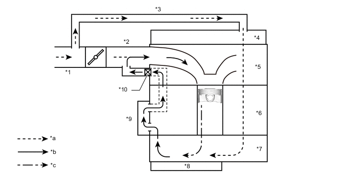
*1 No. 1 Air Cleaner Hose *2 Intake Manifold *3 No. 2 Ventilation Hose *4 Cylinder Head Cover Sub-assembly *5 Cylinder Head Sub-assembly *6 Cylinder Block Sub-assembly *7 Stiffening Crankcase Assembly *8 No. 2 Oil Pan Sub-assembly *9 No. 1 Ventilation Case *10 PCV Valve *a Fresh Air *b Blowby Gas + Fresh Air *c Blowby Gas - -
-