DYNAMIC TORQUE CONTROL 4WD/AWD SYSTEM Pattern Select Switch Sport Mode Circuit
| DTC Code | DTC Name |
|---|---|
| Pattern Select Switch Sport Mode Circuit |
DESCRIPTION
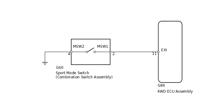
The 4WD ECU assembly switches from normal mode to sport mode when a sport mode ON signal is input from the sport mode switch (combination switch assembly).
WIRING DIAGRAM
CAUTION / NOTICE / HINT
PROCEDURE
INSPECT COMBINATION SWITCH ASSEMBLY
Remove the sport mode switch (combination switch assembly).
Ispect the sport mode switch (combination switch assembly).
Result
Proceed to
OK
NG
CHECK HARNESS AND CONNECTOR (COMBINATION SWITCH ASSEMBLY - BODY GROUND)
-
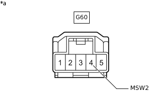
*a
Front view of wire harness connector
(to Sport Mode Switch [Combination Switch Assembly])
Measure the resistance according to the value(s) in the table below.
Standard Resistance
Tester Connection
Condition
Specified Condition
G60-4 (MSW2) - Body ground
Always
Below 1 Ω
Result
Proceed to
OK
NG
NG REPAIR OR REPLACE HARNESS OR CONNECTOR
-
CHECK HARNESS AND CONNECTOR (COMBINATION SWITCH ASSEMBLY - 4WD ECU ASSEMBLY)
Reinstall the sport mode switch (combination switch assembly).
Disconnect the 4WD ECU assembly connector.
-
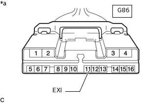
*a
Front view of wire harness connector
(to 4WD ECU Assembly)
Measure the resistance according to the value(s) in the table below.
Standard Resistance
Tester Connection
Condition
Specified Condition
G86-11 (EXI) - Body ground
Sport mode switch on (Push)
Below 1 Ω
Sport mode switch off (Release)
10 kΩ or higher
Result
Proceed to
OK
NG
NG REPAIR OR REPLACE HARNESS OR CONNECTOR