CAMSHAFT REMOVAL
CAUTION / NOTICE / HINT
When replacing the injectors (including shuffling the injectors between the cylinders), common rail, intake manifold or cylinder head, it is necessary to replace the injection pipes with new ones.
When replacing the fuel supply pump, common rail, intake manifold or cylinder head, it is necessary to replace the fuel inlet pipe with a new one.
PROCEDURE
PRECAUTION
Note:After turning the ignition switch off, waiting time may be required before disconnecting the cable from the battery terminal. Therefore, make sure to read the disconnecting the cable from the battery terminal notice before proceeding with work.
DISCONNECT CABLE FROM NEGATIVE BATTERY TERMINAL
Note:When disconnecting the cable, some systems need to be initialized after the cable is reconnected.
Click hereClick hereClick hereClick hereClick hereClick here
REMOVE ENGINE ASSEMBLY
DISCONNECT ENGINE WIRE
REMOVE GENERATOR ASSEMBLY
REMOVE VACUUM PUMP ASSEMBLY
REMOVE IDLER PULLEY COVER PLATE
REMOVE NO. 1 IDLER PULLEY SUB-ASSEMBLY
REMOVE NO. 2 IDLER PULLEY SUB-ASSEMBLY
REMOVE NO. 4 WATER BY-PASS PIPE
REMOVE ENGINE MOUNTING BRACKET
REMOVE V-RIBBED BELT TENSIONER ASSEMBLY
REMOVE DIESEL THROTTLE BODY ASSEMBLY
REMOVE NO. 7 WATER BY-PASS HOSE
DISCONNECT NO. 8 WATER BY-PASS HOSE
REMOVE EGR VALVE BRACKET
REMOVE NO. 2 EGR PIPE SUB-ASSEMBLY
REMOVE ELECTRIC EGR CONTROL VALVE ASSEMBLY
REMOVE ENGINE OIL LEVEL DIPSTICK GUIDE
REMOVE FUEL INLET PIPE SUB-ASSEMBLY
REMOVE INJECTION PIPE SUB-ASSEMBLY
REMOVE NO. 4 FUEL HOSE
REMOVE COMMON RAIL ASSEMBLY
REMOVE INTAKE MANIFOLD INSULATOR
REMOVE DIESEL TURBO PRESSURE SENSOR
REMOVE NO. 1 GAS FILTER
REMOVE GAS FILTER BRACKET
REMOVE ENGINE COVER BRACKET
REMOVE NO. 2 INTAKE MANIFOLD
REMOVE INTAKE MANIFOLD
REMOVE WATER BY-PASS HOSE
REMOVE OIL COOLER ASSEMBLY
REMOVE NO. 6 WATER BY-PASS HOSE
REMOVE NO. 8 WATER BY-PASS HOSE
REMOVE NO. 3 WATER BY-PASS PIPE
REMOVE NO. 1 TURBO OIL PIPE
REMOVE NO. 1 OIL COOLER BRACKET
REMOVE NO. 1 CYLINDER BLOCK INSULATOR
REMOVE NO. 2 WATER BY-PASS PIPE
REMOVE NO. 4 WATER BY-PASS HOSE
REMOVE WATER INLET HOUSING
REMOVE FUEL HOSE PROTECTOR
REMOVE FUEL TUBE SUB-ASSEMBLY
REMOVE NO. 3 FUEL HOSE
REMOVE NO. 2 NOZZLE LEAKAGE PIPE
REMOVE NO. 1 NOZZLE LEAKAGE PIPE
REMOVE NO. 1 NOZZLE HOLDER CLAMP
REMOVE INJECTOR ASSEMBLY
REMOVE NO. 1 VACUUM SWITCHING VALVE ASSEMBLY
REMOVE VACUUM REGULATING VALVE ASSEMBLY
REMOVE VACUUM TRANSMITTING HOSE ASSEMBLY
REMOVE PCV HOSE
REMOVE OIL FILLER CAP SUB-ASSEMBLY
REMOVE CYLINDER HEAD COVER SUB-ASSEMBLY
REMOVE NO. 2 OIL PAN SUB-ASSEMBLY
REMOVE OIL FILTER ELEMENT
REMOVE OIL FILTER BRACKET
REMOVE OIL STRAINER SUB-ASSEMBLY
REMOVE CAMSHAFT POSITION SENSOR
DISCONNECT CRANKSHAFT POSITION SENSOR WIRE HARNESS
REMOVE ENGINE WATER PUMP ASSEMBLY
SET NO. 1 CYLINDER TO TDC / COMPRESSION
REMOVE CRANKSHAFT PULLEY
REMOVE TIMING CHAIN COVER SUB-ASSEMBLY
REMOVE FUEL SUPPLY PUMP ASSEMBLY
REMOVE NO. 1 CHAIN TENSIONER ASSEMBLY
REMOVE CHAIN TENSIONER SLIPPER
REMOVE NO. 1 CHAIN VIBRATION DAMPER
REMOVE CAMSHAFT TIMING SPROCKET
REMOVE OIL PUMP DRIVE GEAR
REMOVE CRANKSHAFT TIMING SPROCKET
REMOVE CAMSHAFT
-
Using the crankshaft pulley bolt, set the No. 1 cylinder to 90° BTDC/compression.
-
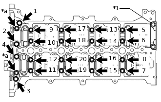
*1
No. 4 Camshaft Bearing Cap
*a
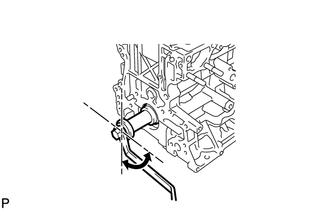
Oil Pipe Seat
Remove the 2 oil pipe seats.
Uniformly loosen the 20 bolts in several steps in the sequence shown in the illustration and remove the bolts.
Remove the 8 No. 3 camshaft bearing caps and No. 1 camshaft bearing cap.
Tip:Do not remove the No. 4 camshaft bearing cap.
Remove the camshaft and No. 2 camshaft.
-
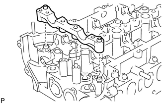
Remove the No. 2 camshaft bearing cap.
-
REMOVE NO. 1 VALVE ROCKER ARM SUB-ASSEMBLY
Remove the 16 No. 1 valve rocker arm sub-assemblies.
REMOVE VALVE LASH ADJUSTER ASSEMBLY
Remove the 16 valve lash adjuster assemblies from the cylinder head sub-assembly.
Tip:Arrange the removed parts in the correct order.