ENGINE UNIT INSTALLATION
CAUTION / NOTICE / HINT
Always be sure to check the tightening torque.
If the pressure lines are leaking after installation, they must be replaced.
Do not overtighten the pressure lines.
All pressure lines may only be reused 3 times. After the 3rd time, they must be replaced.
PROCEDURE
INSTALL DRIVE SHAFT BEARING BRACKET
-
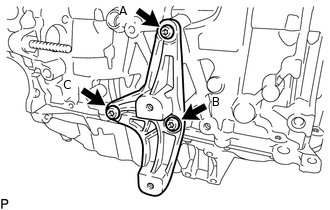
Using a T50 "TORX" socket wrench, install the drive shaft bearing bracket with the 3 bolts.
63.7 N*m
650 kgf*cm
47 ft.*lbf
Note:Temporarily tighten the bolt (A), and then fully tighten the 3 bolts in the order of (B), (A) and (C).
Make sure that the bolts and bolt holes are free of oil. Clean them if necessary.
-
INSTALL VACUUM CONTROL VALVE BRACKET
INSTALL EGR BYPASS VALVE SWITCHING VALVE
INSTALL GLOW PLUG ASSEMBLY
INSTALL COMMON RAIL ASSEMBLY
INSTALL INJECTION PIPE SUB-ASSEMBLY
INSTALL FUEL INLET PIPE SUB-ASSEMBLY
INSTALL NO. 1 ENGINE HANGER
Install the No. 1 engine hanger to the cylinder head sub-assembly with the bolt.
Tip:Refer to "SPECIFICATIONS - STANDARD BOLT" for the tightening torque.
INSTALL NO. 2 ENGINE HANGER
Install the No. 2 engine hanger to the cylinder head sub-assembly with the 2 bolts.
Tip:Refer to "SPECIFICATIONS - STANDARD BOLT" for the tightening torque.
INSTALL EGR VALVE BRACKET
Install the EGR valve bracket to the cylinder head sub-assembly with the 2 bolts.
Tip:Refer to "SPECIFICATIONS - STANDARD BOLT" for the tightening torque.
INSTALL TURBOCHARGER STAY
Install the turbocharger stay with the 2 bolts.
Tip:Refer to "SPECIFICATIONS - STANDARD BOLT" for the tightening torque.
INSTALL NO. 2 TURBO INSULATOR
Install the No. 2 turbo insulator with the 3 bolts.
Tip:Refer to "SPECIFICATIONS - STANDARD BOLT" for the tightening torque.
INSTALL NO. 1 TURBO OIL PIPE
Install the No. 1 turbo oil pipe, 2 nuts and 2 new gaskets with the union bolt.
Union Bolt
35 N*m
357 kgf*cm
26 ft.*lbf
Tip:Refer to "SPECIFICATIONS - STANDARD BOLT" for the tightening torque.
INSTALL EXHAUST MANIFOLD
INSTALL EGR COOLER ASSEMBLY WITH EGR VALVE ASSEMBLY
INSTALL TURBOCHARGER SUB-ASSEMBLY
CONNECT NO. 1 TURBO OIL PIPE
INSTALL TURBO OIL OUTLET PIPE
INSTALL EXHAUST MANIFOLD CONVERTER SUB-ASSEMBLY
INSTALL NO. 1 EXHAUST MANIFOLD HEAT INSULATOR
INSTALL FUEL FEED PIPE SUB-ASSEMBLY
Install the fuel feed pipe sub-assembly with the 2 bolts.
Tip:Refer to "SPECIFICATIONS - STANDARD BOLT" for the tightening torque.
Connect the 2 fuel hoses to the fuel supply pump assembly, and tighten the 2 clamps to secure the 2 hoses.
Connect the fuel return tube to the common rail assembly.
Attach the fuel hose clamp.
Connect the nozzle leakage pipe assembly to the fuel feed pipe sub-assembly.
INSTALL INTAKE MANIFOLD
INSTALL NO. 1 VACUUM PIPE
INSTALL NO. 2 VACUUM HOSE ASSEMBLY
Install the No. 2 vacuum hose assembly to the No. 2 engine hanger with the bolt and nut.
8.5 N*m
87 kgf*cm
75 in.*lbf
CONNECT NO. 2 VACUUM HOSE ASSEMBLY
INSTALL ENGINE OIL LEVEL DIPSTICK GUIDE
INSTALL DIESEL THROTTLE BODY ASSEMBLY
INSTALL V-RIBBED BELT TENSIONER ASSEMBLY
Install the V-ribbed belt tensioner assembly with the 2 bolts.
20 N*m
204 kgf*cm
15 ft.*lbf
INSTALL ENGINE MOUNTING BRACKET
Install the 2 stud bolts to the engine mounting bracket.
10 N*m
102 kgf*cm
7 ft.*lbf
Using an E12 "TORX" socket wrench, install the engine mounting bracket with the 3 bolts.
59 N*m
602 kgf*cm
44 ft.*lbf
INSTALL IDLER PULLEY ASSEMBLY
Using a T50 "TORX" socket wrench, tighten the bolt to install the idler pulley assembly.
40 N*m
408 kgf*cm
30 ft.*lbf
INSTALL GENERATOR ASSEMBLY
INSTALL COMPRESSOR ASSEMBLY WITH PULLEY (w/ Air Conditioning System)
INSTALL V-RIBBED BELT
INSTALL ENGINE WIRE
Install the engine wire to the engine assembly.
INSTALL ENGINE COVER