ENGINE UNIT (w/ Dual VVT-i) REASSEMBLY

Tech Tips
Perform "Inspection After Repairs" after replacing the piston sub-assembly or piston ring Click here.
-
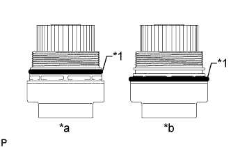
INSTALL TIGHT PLUG
Tech Tips
If coolant leaks from the tight plug or the plug is corroded, replace it.
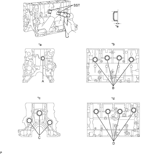
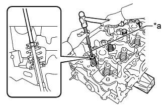
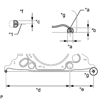
Text in Illustration *a Front Side *b Intake Side *c Rear Side *d Exhaust Side *e 1.0 mm (0.0394 in.) - -
-
Apply adhesive around the tight plugs.
Adhesive Toyota Genuine Adhesive 1324, Three Bond 1324 or equivalent -
Using SST, tap in the tight plug labeled A.
- SST
- 09950-60010 ( 09951-00300 )
- 09950-70010 ( 09951-07100 )
-
Using SST, tap in the 8 tight plugs labeled B and D.
- SST
- 09950-60010 ( 09951-00350 )
- 09950-70010 ( 09951-07100 )
-
Using SST, tap in the tight plugs labeled C.
- SST
- 09950-60010 ( 09951-00400 )
- 09950-70010 ( 09951-07100 )
-
-
INSTALL STUD BOLT
Tech Tips
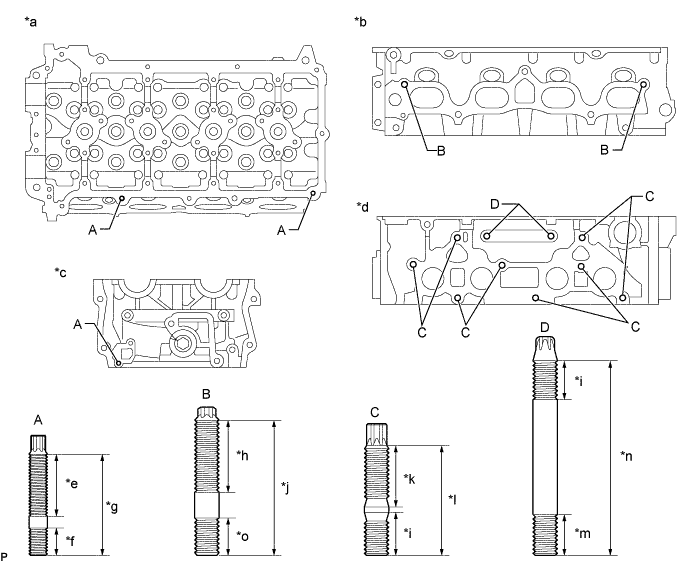
If a stud bolt is deformed or its threads are damaged, replace it.
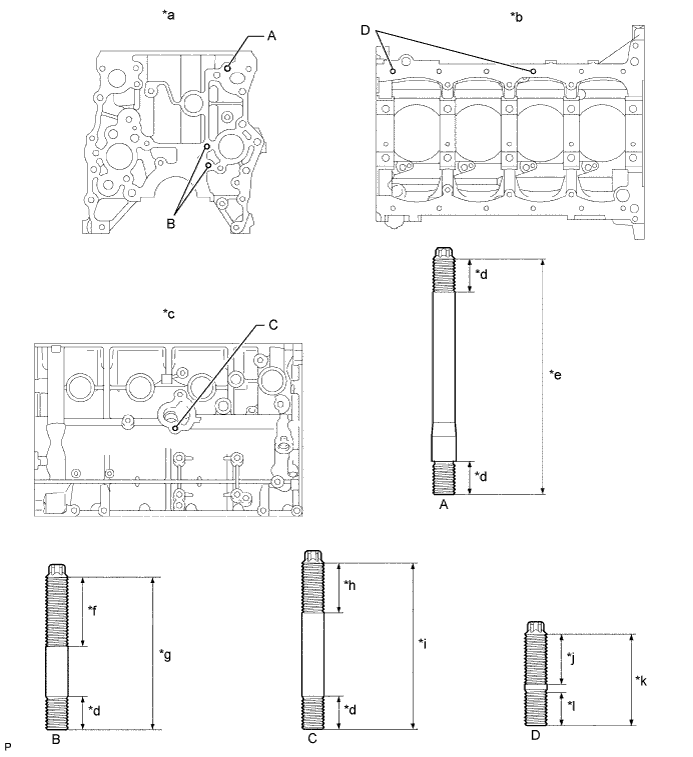
Text in Illustration *a Front Side *b Lower Side *c Exhaust Side *d 12 mm (0.472 in.) *e 81 mm (3.19 in.) *f 25 mm (0.984 in.) *g 56 mm (2.20 in.) *h 18 mm (0.709 in.) *i 60 mm (2.36 in.) *j 20 mm (0.787 in.) *k 35 mm (1.38 in.) *l 13 mm (0.512 in.)
-
Using an E8 "TORX" socket wrench, install the stud bolts labeled A.
- Torque:
- 7.5 N*m { 77 kgf*cm, 66 in.*lbf }
-
Using an E7 "TORX" socket wrench, install the stud bolts labeled B and labeled D.
- Torque:
- 7.5 N*m { 77 kgf*cm, 66 in.*lbf }
-
Apply adhesive to the hole for the stud bolt labeled C on the cylinder block. Using an E7 "TORX" socket wrench, install the stud bolts labeled C.
- Torque:
- 7.5 N*m { 77 kgf*cm, 66 in.*lbf }
Tech Tips
When reusing a stud bolt, apply adhesive to the bolt before installing it.
Adhesive Toyota Genuine Adhesive 1344, Three Bond 1344 or equivalent
-
-
INSTALL STRAIGHT PIN
Tech Tips
It is not necessary to remove a straight pin unless it is being replaced.
-
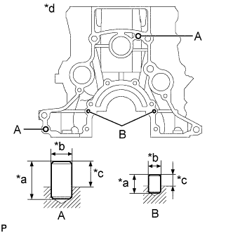
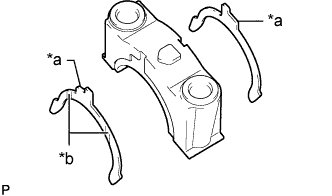
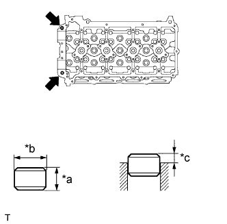
Text in Illustration *a Height *b Wide *c Protrusion Height *d Rear Side Using a plastic-faced hammer, tap in new straight pins to the cylinder block.
Standard Straight Pin Item Height Width Protrusion Pin A 22 mm (0.866 in.) 10 mm (0.394 in.) 13 mm (0.512 in.) Pin B 14 mm (0.551 in.) 6.0 mm (0.236 in.) 5.5 mm (0.217 in.)
-
-
INSTALL RING PIN
Tech Tips
It is not necessary to remove a ring pin unless it is being replaced.
-
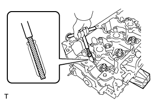
Using a plastic-faced hammer, tap in new ring pins to the cylinder block.
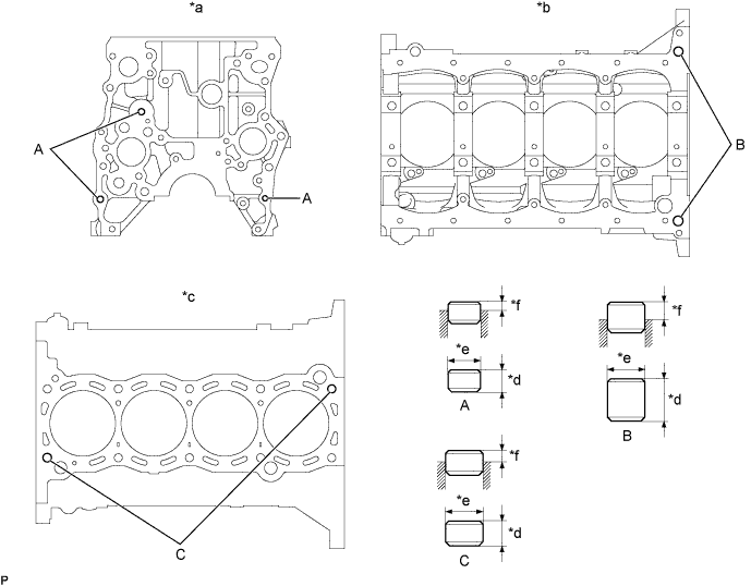
Text in Illustration *a Front Side *b Lower Side *c Upper Side *d Height *e Width *f Protrusion Standard Ring Pin Item Height Width Protrusion Pin A 9.0 mm (0.354 in.) 11 mm (0.433 in.) 3.5 to 4.5 mm (0.138 to 0.177 in.) Pin B 20 mm (0.787 in.) 14 mm (0.511 in.) 7.0 to 9.0 mm (0.276 to 0.354 in.) Pin C 14 mm (0.511 in.) 15 mm (0.591 in.) 7.5 to 9.5 mm (0.295 to 0.374 in.)
-
-
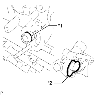
INSTALL NO. 2 BALANCESHAFT DRIVEN GEAR
-
Mount the head portion of the No. 2 balanceshaft in a vise.
Note
Do not damage the No. 2 balanceshaft.
-
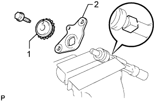
Text in Illustration *1 No. 2 Balanceshaft Driven Gear *2 No. 2 Balanceshaft Thrust Washer Install the No. 2 balanceshaft thrust washer and No. 2 balanceshaft driven gear.
-
Install the bolt.
- Torque:
- 36 N*m { 367 kgf*cm, 27 ft.*lbf }
-
-
INSTALL NO. 2 BALANCESHAFT
-
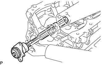
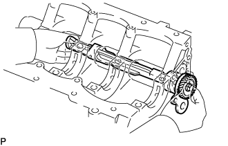
Install the No. 2 balanceshaft to the cylinder block.
Note
When installing the No. 2 balanceshaft, make sure to support the No. 2 balanceshaft with both hands and avoid scratching the No. 2 balanceshaft bearing on the cylinder block side.
-
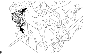
Install the 2 bolts.
- Torque:
- 18 N*m { 184 kgf*cm, 13 ft.*lbf }
-
-
INSTALL NO. 1 BALANCESHAFT DRIVEN GEAR
-
Mount the head portion of the No. 1 balanceshaft in a vise.
Note
Do not damage the No. 1 balanceshaft.
-
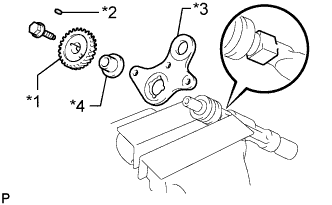
Text in Illustration *1 No. 1 Balanceshaft Driven Gear *2 Sliding Key *3 Balanceshaft Thrust Washer *4 Balanceshaft Thrust Spacer Install the balanceshaft thrust spacer, balanceshaft thrust washer, sliding key and No. 1 balanceshaft driven gear.
-
Install the bolt.
- Torque:
- 36 N*m { 367 kgf*cm, 27 ft.*lbf }
-
-
INSTALL NO. 1 BALANCESHAFT
-
Install the No. 1 balanceshaft to the cylinder block.
Note
When installing the No. 1 balanceshaft, make sure to support the No. 1 balanceshaft with both hands and avoid scratching the No. 1 balanceshaft bearing on the cylinder block side.
-
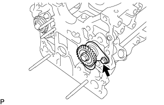
Install the bolt.
- Torque:
- 18 N*m { 184 kgf*cm, 13 ft.*lbf }
-
-
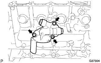
INSTALL CYLINDER BLOCK WATER DRAIN COCK SUB-ASSEMBLY
-
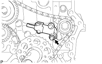
Apply adhesive to the cylinder block water drain cock sub-assembly.
Adhesive Toyota Genuine Adhesive 1324, Three Bond 1324 or equivalent -
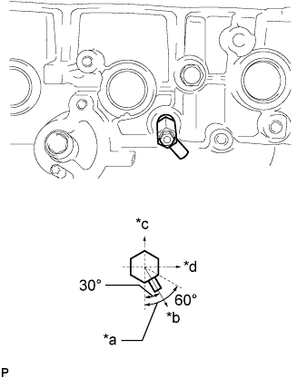
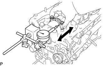
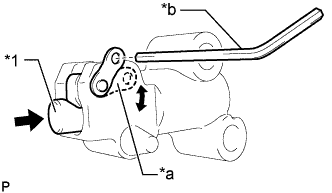
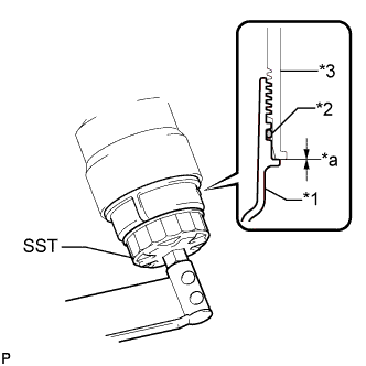
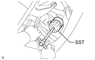
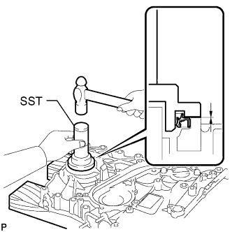
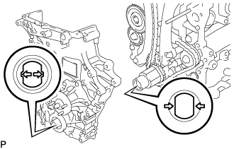
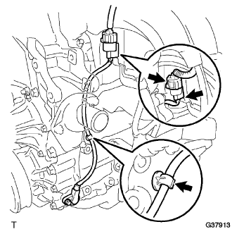
Text in Illustration *a Allowable Range *b Target Direction *c Upper Side *d Front Install the cylinder block water drain cock sub-assembly as shown in the illustration.
- Torque:
- 25 N*m { 250 kgf*cm, 18 ft.*lbf }
Note
-
Do not rotate the cylinder block water drain cock sub-assembly more than 1 revolution (360°) after tightening the cylinder block water drain cock sub-assembly to the specified torque.
-
Do not loosen the cylinder block water drain cock sub-assembly to adjust it. If an adjustment is necessary, remove the cylinder block water drain cock sub-assembly and reinstall it.
-
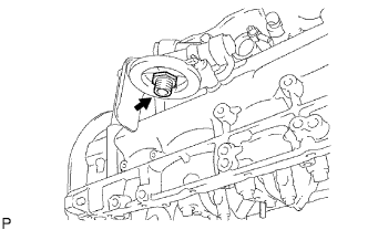
Install the water drain cock plug to the cylinder block water drain cock sub-assembly.
- Torque:
- 13 N*m { 130 kgf*cm, 9 ft.*lbf }
-
-
INSTALL NO. 1 OIL NOZZLE SUB-ASSEMBLY
-
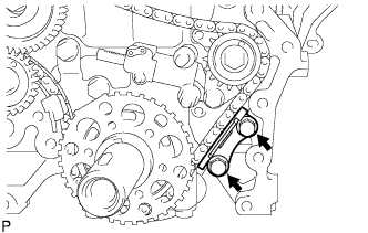
Using an E7 "TORX" socket wrench, install the 4 No. 1 oil nozzle sub-assemblies.
- Torque:
- 7.0 N*m { 71 kgf*cm, 62 in.*lbf }
-
-
INSTALL CONNECTING ROD SMALL END BUSH
-
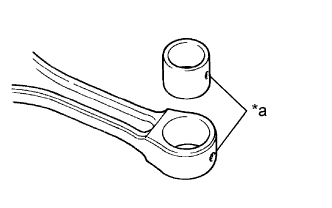
Text in Illustration *a Oil Hole Align the oil holes of a new connecting rod small end bush and the connecting rod.
-
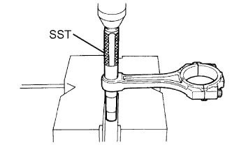
Using SST and a press, press in the connecting rod small end bush.
- SST
- 09222-30010
-
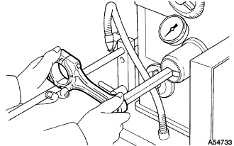
Using a pin hole grinder, hone the connecting rod small end bush to obtain the standard specified clearance Click here between the connecting rod small end bush and piston pin.
-
Check that the piston pin fits at normal room temperature.
-
Coat the piston pin with engine oil, and push it into the connecting rod with your thumb.
-
-
-
INSTALL PISTON WITH PIN SUB-ASSEMBLY
Tech Tips
Perform "Inspection After Repairs" after replacing the piston sub-assembly Click here.
-
Assemble the piston and connecting rod.
-
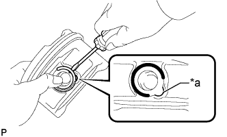
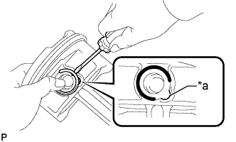
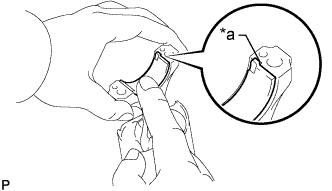
Text in Illustration *a Service Hole Cutout Portion Using a screwdriver, install a new snap ring at one end of the piston pin hole.
Tech Tips
Make sure that the end gap of the snap ring is not aligned with the service hole cutout portion of the piston.
-
Gradually heat the piston to approximately 80 to 90°C (176 to 194°F).
-
Coat the piston pin with engine oil.
-
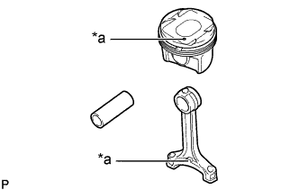
Text in Illustration *a Front Mark Align the front marks of the piston and connecting rod and push in the piston pin with your thumb.
Tech Tips
The piston and pin are a matched set.
-
Text in Illustration *a Service Hole Cutout Portion Using a screwdriver, install a new snap ring at the other end of the piston pin hole.
Tech Tips
Make sure that the end gap of the snap ring is not aligned with the service hole cutout portion of the piston.
-
Check the fitting condition between the piston and piston pin by trying to move the piston back and forth on the piston pin.
-
-
-
INSTALL PISTON RING SET
Tech Tips
Perform "Inspection After Repairs" after replacing the piston ring Click here.
-
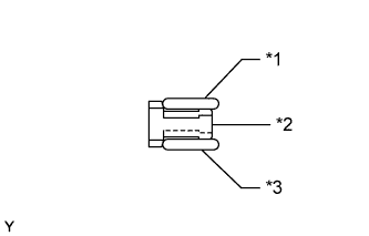
Text in Illustration *1 Upper Oil Ring Side Rail *2 Oil Ring Expander *3 Lower Oil Ring Side Rail Install the oil ring expander and 2 oil ring side rails by hand.
-
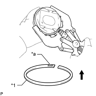
Text in Illustration *1 No. 2 Compression Ring *a Code Mark (2N) 
Upward Using a piston ring expander, install the 2 compression rings with the code mark as shown in the illustration.
Note
-
The No. 1 compression ring is reversible.
-
Install the No. 2 compression ring with the code mark (2N) facing upward.
-
-
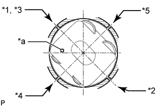
Text in Illustration *1 No. 1 Compression Ring *2 No. 2 Compression Ring *3 Oil Ring Expander *4 Upper Oil Ring Side Rail *5 Lower Oil Ring Side Rail *a Front Mark Position the piston rings so that the ring ends are as shown in the illustration.
Note
Do not align the compression ring ends.
-
-
INSTALL CRANKSHAFT BEARING
Note
Do not apply engine oil to the contact area or backside of the crankshaft bearing.
Tech Tips
The crankshaft bearing cap bolts are tightened in 2 progressive steps.
-
Clean the main journal, and both surfaces of the crankshaft bearing.
-
Install the upper crankshaft bearing.
-
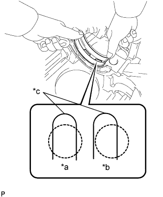
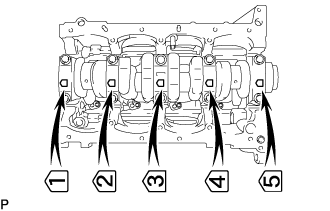
Text in Illustration *a CORRECT *b INCORRECT *c Oil Groove Install the upper crankshaft bearing to the cylinder block as shown in the illustration.
Reference (Difference in Dimension of Cylinder Block and Bearing) Item Specified Condition # 1, 5 journal 3.75 mm (0.1476 in.) # 3 journal 1.75 mm (0.0689 in.) # 2, 4 journal 2.75 mm (0.1083 in.) Note
-
Do not apply engine oil to the upper crankshaft bearings or their contact surfaces.
-
Both sides of the oil groove in the cylinder block should be visible through the oil feed holes in the bearing. The amount visible on each side of the holes should be equal.
-
-
-
Install the lower crankshaft bearing.
-
Install the lower crankshaft bearing to the crankshaft bearing cap.
-
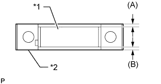
Text in Illustration *1 Lower Crankshaft Bearing *2 Crankshaft Bearing Cap Using a vernier caliper, measure the distance between the crankshaft bearing cap edge and lower crankshaft bearing edge.
Dimension (A - B) or (B - A) 0.3 mm (0.0118 in.) or less Reference (Dimension of (A) or (B)) Item Specified Condition # 1, 5 journal 3.75 mm (0.1476 in.) # 3 journal 1.75 mm (0.0689 in.) # 2, 4 journal 2.75 mm (0.108 in.) Note
Do not apply engine oil to the crankshaft bearings or their contact surfaces.
-
-
With the upper crankshaft bearing and lower crankshaft bearing installed, use a plastic-faced hammer to install the crankshaft bearing caps to the cylinder block.
Note
Make sure that the crankshaft bearing caps are installed in the correct positions and facing in the correct direction.
-
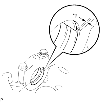
Text in Illustration *a Misalignment Using a vernier caliper, measure the amount of misalignment between the upper crankshaft bearing and lower crankshaft bearing as shown in the illustration.
Standard misalignment 0.9 mm (0.0354 in.) or less -
Remove the crankshaft bearing cap.
-
Apply engine oil to the upper crankshaft thrust washers.
-
Text in Illustration *a Oil Groove Install the 2 upper crankshaft thrust washers to the No. 3 journal position of the cylinder block with the oil grooves facing outward.
Note
Be careful when installing the upper and lower crankshaft thrust washers as they are similar but cannot be interchanged.
-
Text in Illustration *a Claw *b Oil Groove Install the 2 lower crankshaft thrust washers to the No. 3 crankshaft bearing cap with the grooves facing outward.
Note
Be careful when installing the upper and lower crankshaft thrust washers as they are similar but cannot be interchanged. The lower crankshaft thrust washers have a claw as shown in the illustration.
-
-
Apply engine oil to the lower crankshaft bearing.
-
-
INSTALL CRANKSHAFT
-
Apply engine oil to the upper crankshaft bearing, and then place the crankshaft on the cylinder block.
-
Install the 5 crankshaft bearing caps to their proper locations.
-
Install the crankshaft bearing cap bolts.
-
Apply a light coat of engine oil to the threads and under the heads of the bearing cap bolts.
-
Temporarily install the crankshaft bearing cap bolts.
Tech Tips
The crankshaft bearing cap bolts are tightened in 2 progressive steps.
-
Step 1:
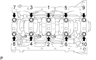
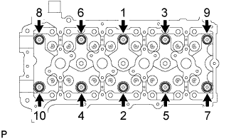
Uniformly tighten the 10 crankshaft bearing cap bolts in the sequence shown in the illustration.
- Torque:
- 39 N*m { 398 kgf*cm, 29 ft.*lbf }
If any of the crankshaft bearing cap bolts does not meet the torque specification, replace the crankshaft bearing cap bolt.
-
Mark the front of the crankshaft bearing cap bolts with paint.
-
Step 2:
Tighten the crankshaft bearing cap bolts 90° in the sequence shown in step 1.
-
Check that the paint marks are now at a 90° angle to the front.
-
-
Check that the crankshaft turns smoothly.
-
-
INSPECT CRANKSHAFT THRUST CLEARANCE
-
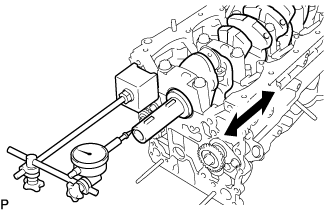
Using a dial indicator, measure the thrust clearance while prying the crankshaft back and forth with a screwdriver.
Standard thrust clearance 0.02 to 0.22 mm (0.000787 to 0.00866 in.) Maximum thrust clearance 0.30 mm (0.0118 in.) If the thrust clearance is more than the maximum, replace the thrust washers as a set. If necessary, replace the crankshaft.
Thrust washer thickness 2.440 to 2.490 mm (0.0961 to 0.0980 in.)
-
-
INSTALL CONNECTING ROD BEARING
-
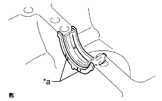
Text in Illustration *a Claw Align the connecting rod bearing claw with the groove of the connecting rod or connecting rod cap.
-
Install the bearings in the connecting rod and connecting rod cap.
Note
Clean the backside of the bearing and the bearing surface of the connecting rod.
-
-
INSTALL PISTON SUB-ASSEMBLY WITH CONNECTING ROD
-
Apply engine oil to the cylinder walls, the pistons, and the surfaces of the connecting rod bearings.
-
Text in Illustration *1 No. 1 Compression Ring *2 No. 2 Compression Ring *3 Oil Ring Expander *4 Upper Oil Ring Side Rail *5 Lower Oil Ring Side Rail *a Front Mark Position the piston rings so that the ring ends are as shown in the illustration.
Note
Do not align the compression ring ends.
-
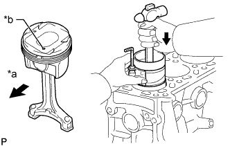
Text in Illustration *a Front *b Front Mark Using a piston ring compressor, push the numbered piston and connecting rod assembly into the correct cylinder with the front mark of the piston facing forward.
-
Match the numbered connecting rod cap with the correct connecting rod.
-
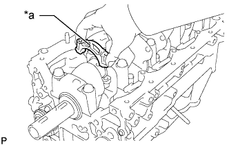
Text in Illustration *a Front Mark Check that the front mark of the connecting rod cap is facing forward.
-
Install the connecting rod cap bolts.
Tech Tips
The connecting rod cap bolts are tightened in 2 progressive steps.
-
Apply a light coat of engine oil to the threads and under the heads of the connecting rod cap bolts.
-
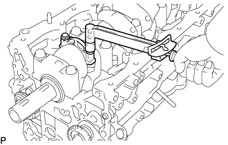
Step 1:
Install and alternately tighten the bolts of the connecting rod cap in several steps.
- Torque:
- 25 N*m { 250 kgf*cm, 18 ft.*lbf }
-
Mark the front of each connecting rod cap bolt with paint.
-
Step 2:
Tighten the cap bolts 90° as shown.
-
Check that the paint marks are now at a 90° angle to the front.
-
-
Check that the crankshaft turns smoothly.
-
-
INSPECT CONNECTING ROD THRUST CLEARANCE
-
Using a dial indicator, measure the thrust clearance while moving the connecting rod back and forth.
Standard thrust clearance 0.15 to 0.35 mm (0.00591 to 0.0138 in.) Maximum thrust clearance 0.40 mm (0.0157 in.) If the thrust clearance is more than the maximum, replace the connecting rod assembly. If necessary, replace the crankshaft.
-
-
INSTALL INTAKE VALVE GUIDE BUSH
-
Using a caliper gauge, measure the bush bore diameter of the cylinder head.
Standard Bush Bore Diameter Item Specified Condition STD 10.285 to 10.306 mm (0.405 to 0.406 in.) O/S 0.05 10.335 to 10.356 mm (0.407 to 0.408 in.) If the bush bore diameter of the cylinder head is more than 10.306 mm (0.406 in.), machine the bush bore so that the diameter is between 10.335 and 10.356 mm (0.407 and 0.408 in.).
If the bush bore diameter of the cylinder head is more than 10.356 mm (0.408 in.), replace the cylinder head sub-assembly.
-
Select a new intake valve guide bush.
New Valve Guide Bush Item Specified Condition Bush Diameter 10.333 to 10.344 mm (0.4068 to 0.4072 in.) 10.383 to 10.394 mm (0.4088 to 0.4092 in.) Bush to be Used STD O/S 0.05 Tech Tips
Standard intake valve guide bush length: 43.0 to 44.0 mm (1.69 to 1.73 in.)
-
Heat the cylinder head sub-assembly to 80 to 100°C (176 to 212°F).
-
Place the cylinder head sub-assembly on wooden blocks.
-
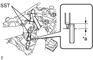
Text in Illustration *a Protrusion Height Using SST and a hammer, tap in a new intake valve guide bush to the specified protrusion height.
- SST
- 09201-01055
- 09950-70010 ( 09951-07100 )
Standard protrusion height 9.8 to 10.2 mm (0.386 to 0.402 in.) -
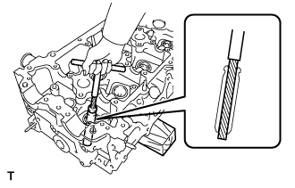
Using a sharp 5.5 mm reamer, ream the intake valve guide bush to obtain the standard clearance between the intake valve guide bush and valve stem.
Standard oil clearance 0.025 to 0.060 mm (0.000984 to 0.00236 in.)
-
-
INSTALL EXHAUST VALVE GUIDE BUSH
-
Using a caliper gauge, measure the bush bore diameter of the cylinder head.
Standard Bush Bore Diameter Item Specified Condition STD 10.285 to 10.306 mm (0.405 to 0.406 in.) O/S 0.05 10.335 to 10.356 mm (0.407 to 0.408 in.) If the bush bore diameter of the cylinder head is more than 10.306 mm (0.406 in.), machine the bush bore so that the diameter is between 10.335 and 10.356 mm (0.407 and 0.408 in.).
If the bush bore diameter of the cylinder head is more than 10.356 mm (0.408 in.), replace the cylinder head sub-assembly.
-
Select a new exhaust valve guide bush.
New Valve Guide Bush Item Specified Condition Bush Diameter 10.333 to 10.344 mm (0.4068 to 0.4072 in.) 10.383 to 10.394 mm (0.4088 to 0.4092 in.) Bush to be Used STD O/S 0.05 Tech Tips
Standard exhaust valve guide bush length: 43.0 to 44.0 mm (1.69 to 1.73 in.)
-
Heat the cylinder head sub-assembly to 80 to 100°C (176 to 212°F).
-
Place the cylinder head sub-assembly on wooden blocks.
-
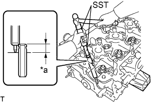
Text in Illustration *a Protrusion Height Using SST and a hammer, tap in a new exhaust valve guide bush to the specified protrusion height.
- SST
- 09201-01055
- 09950-70010 ( 09951-07100 )
Standard protrusion height 7.6 to 8.0 mm (0.299 to 0.315 in.) -
Using a sharp 5.5 mm reamer, ream the exhaust valve guide bush to obtain the standard clearance between the exhaust valve guide bush and valve stem.
Standard oil clearance 0.030 to 0.065 mm (0.00118 to 0.00256 in.)
-
-
INSTALL CAMSHAFT BEARING CAP SETTING RING PIN
Note
It is not necessary to remove a ring pin unless it is being replaced.
-
Remove the ring pins.
-
Using a plastic-faced hammer, tap in a new ring pin until the pin stops.
Standard Ring Pin Item Height Width Protrusion Height Ring pin 7 mm (0.276 in.) 10 mm (0.394 in.) 2.5 to 3.8 mm (0.0984 to 0.150 in.) Text in Illustration *a Height *b Width *c Protrusion Height
-
-
INSTALL STUD BOLT
Note
If a stud bolt is deformed or its threads are damaged, replace it.
-
Using E6, E7 and E8 "TORX" socket wrenches, install the stud bolts.
Text in Illustration *a Cylinder Head Upper Side *b Intake Side *c Front Side *d Exhaust Side *e 21 mm (0.827 in.) *f 9 mm (0.354 in.) *g 34 mm (1.34 in.) *h 18 mm (0.709 in.) *i 13 mm (0.512 in.) *j 44 mm (1.73 in.) *k 20 mm (0.787 in.) *l 35 mm (1.38 in.) *m 14 mm (0.551 in.) *n 63 mm (2.48 in.) *o 12 mm (0.472 in.) - - - Torque:
- for stud bolt A
- 3.0 N*m { 31 kgf*cm, 27 in.*lbf }
- for stud bolt B and C
- 7.5 N*m { 76 kgf*cm, 66 in.*lbf }
-
-
INSTALL NO. 1 HEAD STRAIGHT SCREW PLUG
Note
If coolant leaks from a No. 1 head straight screw plug or a plug is corroded, replace it.
-
Using a 10 mm hexagon wrench, install 3 new gaskets and the No. 1 head straight screw plugs.
- Torque:
- 44 N*m { 449 kgf*cm, 32 ft.*lbf }
-
-
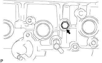
INSTALL NO. 2 HEAD STRAIGHT SCREW PLUG
Note
If coolant leaks from the No. 2 head straight screw plug or the plug is corroded, replace it.
-
Using a 19 mm hexagon wrench, install a new gasket and the No. 2 head straight screw plug.
- Torque:
- 140 N*m { 1428 kgf*cm, 103 ft.*lbf }
-
-
INSTALL OIL CONTROL VALVE FILTER
-
Check that no foreign matter is on the mesh part of the filter.
If foreign objects are present, clean the part thoroughly.
-
Using an 8 mm hexagon wrench, install a new gasket and the oil control valve filter with the screw plug.
- Torque:
- 30 N*m { 306 kgf*cm, 22 ft.*lbf }
-
-
INSTALL VALVE SPRING SEAT
-
Install the 16 valve spring seats to the cylinder head sub-assembly.
-
-
INSTALL VALVE STEM OIL SEAL
-
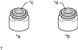
Text in Illustration *a Intake Side *b Exhaust Side *c Gray *d Black Apply a light coat of engine oil to new valve stem oil seals.
Note
Pay attention when installing the intake and exhaust valve stem oil seals. Installing an intake valve stem oil seal to the exhaust side or installing an exhaust valve stem oil seal to the intake side can cause installation problems later.
Tech Tips
The intake valve stem oil seals are gray and the exhaust valve stem oil seals are black.
-
Text in Illustration *1 Valve Stem Oil Seal Using SST, push in the 16 valve stem oil seals to install them.
- SST
- 09201-41020
Note
Failure to use SST will cause the seal to be damaged or improperly seated.
-
-
INSTALL INTAKE VALVE
-
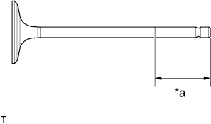
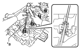
Text in Illustration *a 30 mm (1.18 in.) or more Apply plenty of engine oil to the tip area of the intake valve shown in the illustration.
-
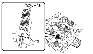
Text in Illustration *a Narrow *b Wide Install the intake valve, inner compression spring and valve spring retainer to the cylinder head sub-assembly.
Note
Install the same parts in the same combination to the original locations.
-
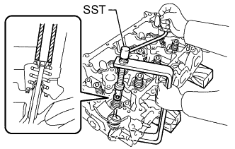
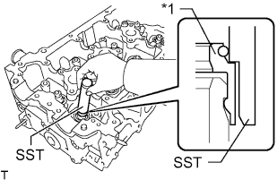
Using SST and wooden blocks, compress the inner compression spring and install the 2 valve spring retainer locks.
- SST
- 09202-70020
- 09202-00021
-
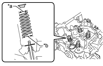
Text in Illustration *a 5 mm Pin Punch Using a 5 mm pin punch and plastic-faced hammer, lightly tap the valve stem tip to ensure a proper fit.
Note
Do not damage the valve stem tip.
-
-
INSTALL EXHAUST VALVE
-
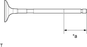
Text in Illustration *a 30 mm (1.18 in.) or more Apply plenty of engine oil to the tip area of the exhaust valve shown in the illustration.
-
Text in Illustration *a Narrow *b Wide Install the exhaust valve, inner compression spring and valve spring retainer to the cylinder head sub-assembly.
Note
Install the same parts in the same combination to the original locations.
-
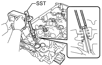
Using SST and wooden blocks, compress the inner compression spring and install the 2 valve spring retainer locks.
- SST
- 09202-70020
- 09202-00021
-
Text in Illustration *a 5 mm Pin Punch Using a 5 mm pin punch and plastic-faced hammer, lightly tap the valve stem tip to ensure a proper fit.
Note
Do not damage the valve stem tip.
-
-
INSTALL CRANKSHAFT PULLEY SET KEY
-
Install the 2 crankshaft pulley set keys to the crankshaft.
-
-
INSTALL NO. 4 CHAIN VIBRATION DAMPER
-
Install the No. 4 chain vibration damper with the 2 bolts.
- Torque:
- 18 N*m { 184 kgf*cm, 13 ft.*lbf }
-
-
INSTALL NO. 2 CHAIN SUB-ASSEMBLY
-
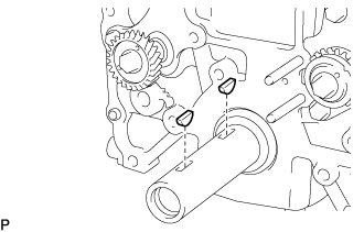
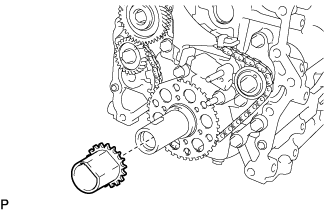
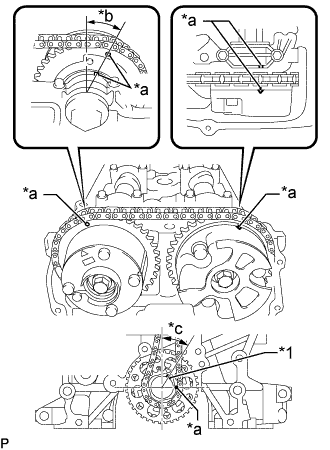
Install the No. 2 crankshaft timing sprocket as shown in the illustration.
Note
Check that the No. 1 cylinder is at TDC and that the weights of the No. 1 and No. 2 balanceshafts are at the bottom side.
Tech Tips
Install the No. 2 crankshaft timing sprocket with the front mark facing forward.
-
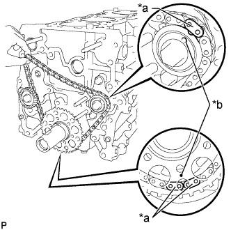
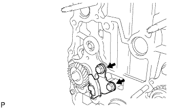
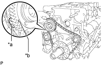
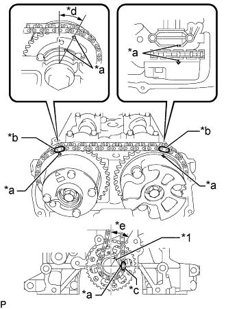
Text in Illustration *a Mark Plate *b Timing Mark As shown in the illustration, install the No. 2 chain sub-assembly on the No. 2 crankshaft timing sprocket and No. 2 balanceshaft driven gear with the painted marks aligned with the timing marks on the sprocket and gear.
-
Text in Illustration *a Mark Plate *b Timing Mark Fit the other mark link of the No. 2 crankshaft timing sprocket behind the large timing mark of the balanceshaft drive gear sub-assembly.
-
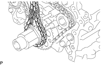
Insert the balanceshaft drive gear shaft through the balanceshaft drive gear sub-assembly so that it fits into the thrust plate hole.
-
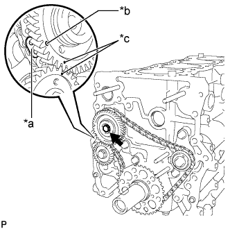
Text in Illustration *a Mark Plate *b Large Timing Mark *c Small Timing Mark Align the small timing mark of the balanceshaft drive gear sub-assembly with the timing mark of the No. 1 balanceshaft driven gear.
-
Install the bolt to the balanceshaft drive gear sub-assembly and tighten it.
- Torque:
- 25 N*m { 255 kgf*cm, 18 ft.*lbf }
-
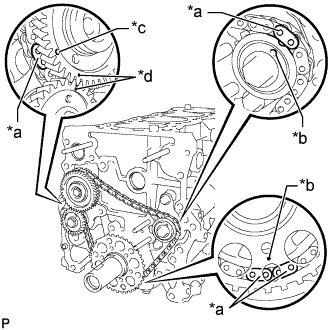
Text in Illustration *a Mark Plate *b Timing Mark *c Large Timing Mark *d Small Timing Mark Check that each timing mark is matched with the corresponding mark link.
Note
Check that the No. 1 cylinder is at TDC and that the weights of the No. 1 balanceshaft and No. 2 balanceshaft are at the bottom side.
-
-
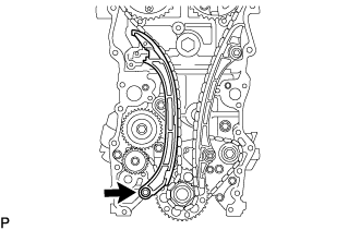
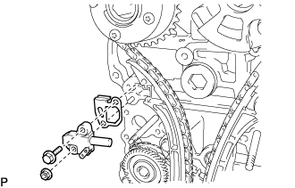
INSTALL NO. 2 CHAIN TENSIONER ASSEMBLY
-
Install the No. 2 chain tensioner assembly with the nut.
- Torque:
- 18 N*m { 184 kgf*cm, 13 ft.*lbf }
Note
Assemble the No. 2 chain tensioner assembly with the pin installed, then remove the pin after assembly. When doing this, do not push the chain vibration damper against the No. 2 chain sub-assembly.
-
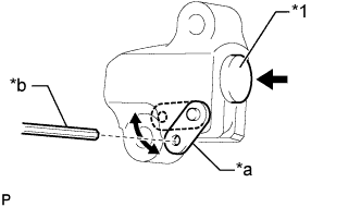
Text in Illustration *1 Plunger *a Stopper Plate *b Hexagon Wrench Move the stopper plate downward to release the lock, and push the plunger deep into the tensioner.
-
Move the stopper plate upward to set the lock, and insert a hexagon wrench into the stopper plate hole.
-
-
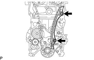
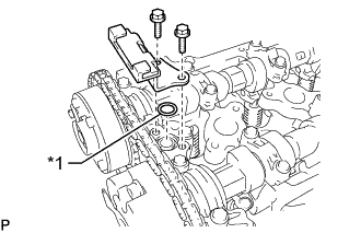
INSTALL NO. 3 CHAIN VIBRATION DAMPER
-
Install the No. 3 chain vibration damper with the 2 bolts.
- Torque:
- 18 N*m { 184 kgf*cm, 13 ft.*lbf }
-
-
INSTALL NO. 2 CHAIN VIBRATION DAMPER
-
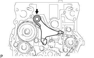
Install the No. 2 chain vibration damper with the bolt.
- Torque:
- 27 N*m { 270 kgf*cm, 20 ft.*lbf }
-
-
INSTALL NO. 1 HEAD TAPER SCREW PLUG
-
Install the No. 1 head taper screw plug to the cylinder block.
- Torque:
- 25 N*m { 250 kgf*cm, 18 ft.*lbf }
-
-
INSTALL OIL FILTER BRACKET SUB-ASSEMBLY (for Type B)
-
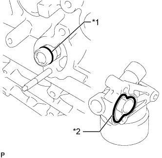
Text in Illustration *1 O-ring *2 Oil Filter Bracket Gasket Install a new oil filter bracket gasket to the oil filter bracket sub-assembly.
-
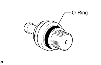
Install a new O-ring to the oil filter bracket union.
Note
Apply a light coat of engine oil to the new O-ring and oil filter bracket sub-assembly.
-
Install 2 new gaskets and the 2 screw plugs to the oil filter bracket sub-assembly.
- Torque:
- 49 N*m { 500 kgf*cm, 36 ft.*lbf }
-
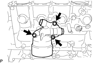
Install the oil filter bracket sub-assembly with the 2 bolts and nut.
- Torque:
- 25 N*m { 255 kgf*cm, 18 ft.*lbf }
-
-
INSTALL OIL FILTER BRACKET SUB-ASSEMBLY (for Type A)
-
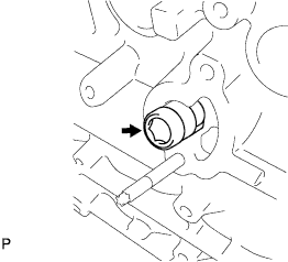
Using a hexagon wrench, install the oil filter bracket union.
- Torque:
- 25 N*m { 250 kgf*cm, 18 ft.*lbf }
-
Text in Illustration *1 O-ring *2 Oil Filter Bracket Gasket Install a new oil filter bracket gasket to the oil filter bracket sub-assembly.
-
Install a new O-ring to the oil filter bracket union.
Note
Apply a light coat of engine oil to the new O-ring and oil filter bracket sub-assembly.
-
Install 2 new gaskets and the 2 screw plugs to the oil filter bracket sub-assembly.
- Torque:
- 49 N*m { 500 kgf*cm, 36 ft.*lbf }
-
Install the oil filter bracket sub-assembly with the 2 bolts and nut.
- Torque:
- 25 N*m { 255 kgf*cm, 18 ft.*lbf }
-
Using a 27 mm socket wrench, install the oil filter union.
- Torque:
- 43 N*m { 439 kgf*cm, 32 ft.*lbf }
-
-
INSTALL OIL FILTER ELEMENT (for Type B)
-
Clean the inside of the oil filter cap, its threads and its O-ring groove.
-
Text in Illustration *1 O-Ring (for Cap) *a CORRECT *b INCORRECT Apply a small amount of engine oil to a new O-ring (for cap) and install it to the oil filter cap.
Note
-
Be sure to install the O-ring (for cap) in the proper location, otherwise oil may leak.
-
Do not twist the O-ring (for cap).
-
-
Set a new oil filter element in the oil filter cap.
-
Remove any dirt or foreign matter from the installation surface of the engine.
-
Apply a small amount of engine oil to the O-ring (for cap) again and temporarily install the oil filter cap.
-
Text in Illustration *1 Oil Filter Cap *2 O-Ring (for Cap) *3 Oil Filter Bracket *a No Gap Using SST, tighten the oil filter cap.
- SST
- 09228-06501
- Torque:
- 25 N*m { 255 kgf*cm, 18 ft.*lbf }
-
-
INSTALL OIL FILTER SUB-ASSEMBLY (for Type A)
-
Check and clean the oil filter installation surface.
-
Apply clean engine oil to the gasket of a new oil filter sub-assembly.
-
Lightly screw the oil filter sub-assembly into place, and tighten it until the gasket contacts the seat.
-
Using SST, tighten the oil filter sub-assembly.
- SST
- 09228-07501
When using a torque wrench Tighten the oil filter sub-assembly. - Torque:
- 17 N*m { 175 kgf*cm, 13 ft.*lbf }
When not using a torque wrench Tighten the oil filter sub-assembly an additional 3/4 turn.
-
-
INSTALL REAR CRANKSHAFT OIL SEAL
-
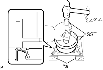
Text in Illustration *a Wooden Blocks Place the rear engine oil seal retainer on wooden blocks.
-
Using SST, tap in a new rear crankshaft oil seal until its surface is flush with the rear engine oil seal retainer edge.
- SST
- 09223-15030
- 09950-70010 ( 09951-07150 )
Note
-
Keep the lip free from foreign matter.
-
Do not tap the rear crankshaft oil seal at an angle.
-
-
INSTALL REAR ENGINE OIL SEAL RETAINER
-
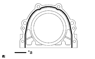
Text in Illustration *a Seal Packing Apply seal packing in a continuous bead as shown in the illustration.
Seal packing Toyota Genuine Seal Packing Black, Three Bond 1207B or equivalent Standard seal width 2.5 to 3.5 mm (0.0984 to 0.138 in.) Note
-
Remove any oil from the contact surface.
-
Install the crankcase within 3 minutes after applying seal packing.
-
Do not start the engine for at least 4 hours after installing.
-
-
Install the rear engine oil seal retainer with the 6 bolts.
- Torque:
- 13 N*m { 133 kgf*cm, 10 ft.*lbf }
Note
Wipe off any seal packing that has leaked out within 10 minutes.
-
-
INSTALL CYLINDER HEAD GASKET
-
Remove any old packing (FIPG) material and be careful not to drop any oil on the contact surfaces of the cylinder head sub-assembly or cylinder block.
-
Text in Illustration *1 Cylinder Head Gasket *a 7.0 to 9.0 mm (0.276 to 0.354 in.) *b 5.0 to 7.0 mm (0.197 to 0.276 in.) *c 3.0 to 5.0 mm (0.118 to 0.197 in.) *d 166.25 mm (6.55 in.) *e 62.25 mm (2.46 in.) *f Side View *g View A Apply seal packing to a new cylinder head gasket as shown in the illustration.
Seal Packing Toyota Genuine Seal Packing Black, Three Bond 1207 B or equivalent. Note
-
Be sure to clean and degrease the contact surfaces.
-
Apply seal packing to the bead on the cylinder head gasket.
-
Install the cylinder head gasket within 3 minutes and tighten the cylinder head set bolts within 15 minutes after applying seal packing.
-
-
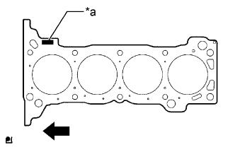
Text in Illustration *a Lot No. Engine Front Place the gasket on the cylinder block surface with the lot No. stamp facing upward.
Note
-
Remove any oil from the contact surface.
-
Make sure that the cylinder head gasket is installed in the correct direction.
-
-
-
INSTALL CYLINDER HEAD SUB-ASSEMBLY
Tech Tips
-
Perform "Inspection After Repairs" after replacing the cylinder head sub-assembly Click here.
-
The cylinder head set bolts are tightened in 3 successive steps.
-
Place the cylinder head sub-assembly on the cylinder block.
Note
-
Make sure that no oil is on the mounting surface of the cylinder head sub-assembly.
-
Place the cylinder head sub-assembly on the cylinder block gently so as not to damage the gasket with the bottom part of the head.
-
-
Install the plate washers to the cylinder head set bolts.
-
Apply a light coat of engine oil to the threads and under the heads of the cylinder head set bolts.
-
Step 1:
Using several steps, install and uniformly tighten the 10 cylinder head set bolts with plate washers in the sequence shown in the illustration.
- Torque:
- 39 N*m { 398 kgf*cm, 29 ft.*lbf }
-
Mark the front of each cylinder head set bolt head with paint.
-
Step 2:
Tighten the cylinder head set bolts 90° in the sequence shown in step 1.
-
Step 3:
Tighten the cylinder head set bolts another 90° in the sequence shown in step 1.
-
Check that the paint marks are now at a 180° angle to the front.
-
-
INSTALL CAMSHAFT TIMING EXHAUST GEAR ASSEMBLY
Tech Tips
Perform "Inspection After Repairs" after replacing the camshaft timing exhaust gear assembly Click here.
-
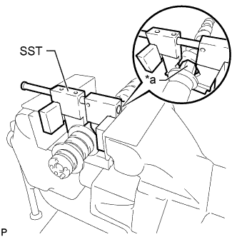
Text in Illustration *a Hexagonal Portion Using SST, grip the hexagonal portion, and then secure the SST and No. 2 camshaft in a vise as shown in the illustration.
- SST
- 09212-31010
Note
-
Do not damage the No. 2 camshaft.
-
Never grip areas other than the hexagonal portion, as this may cause damage.
-
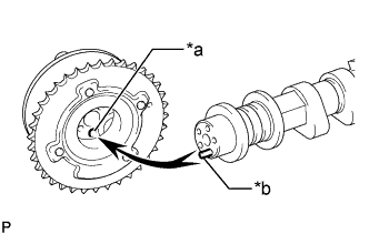
Text in Illustration *a Straight Pin Hole *b Straight Pin Align and attach the straight pin of the No. 2 camshaft with the straight pin hole of the camshaft timing exhaust gear assembly.
-
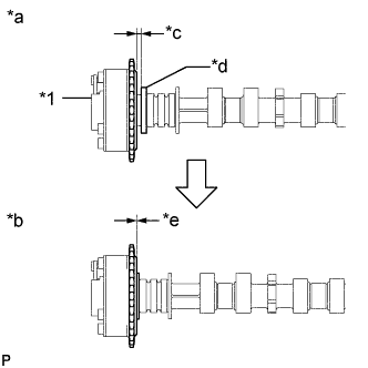
Text in Illustration *1 Camshaft Timing Exhaust Gear Assembly *a INCORRECT *b CORRECT *c Clearance *d Camshaft Flange *e No Clearance Check that there is no clearance between the camshaft timing exhaust gear assembly and camshaft flange.
Note
Be sure not to remove the other 4 bolts. If removing the bolts, exchange the camshaft timing exhaust gear assembly.
-
Fix the camshaft timing exhaust gear assembly with the flange bolt.
- Torque:
- 78 N*m { 795 kgf*cm, 58 ft.*lbf }
-
-
INSTALL CAMSHAFT TIMING GEAR ASSEMBLY
Tech Tips
Perform "Inspection After Repairs" after replacing the camshaft timing gear assembly Click here.
-
Text in Illustration *a Hexagonal Portion Using SST, grip the hexagonal portion, and then secure the SST and camshaft in a vise as shown in the illustration.
- SST
- 09212-31010
Note
-
Do not damage the camshaft.
-
Never grip areas other than the hexagonal portion, as this may cause damage.
-
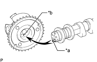
Text in Illustration *a Straight Pin *b Straight Pin Hole Align the straight pin hole and straight pin and install the camshaft timing gear assembly to the camshaft.
-
Lightly press the gear against the camshaft and turn the gear. Push further at the position where the straight pin enters the straight pin hole.
Note
Be sure not to turn the camshaft timing gear assembly in the retard direction (the right angle).
-
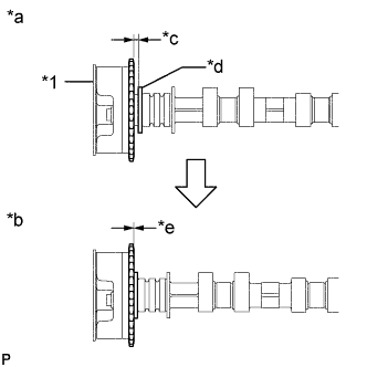
Text in Illustration *1 Camshaft Timing Gear Assembly *a INCORRECT *b CORRECT *c Clearance *d Camshaft Flange *e No Clearance Check that there is no clearance between the camshaft timing gear assembly and the flange of the camshaft.
Note
-
Since the thrust clearance of the camshaft is small, the camshaft must be kept level while it is being removed. If the camshaft is not kept level, the portion of the cylinder head receiving the shaft thrust may crack or be damaged, causing the camshaft to seize or break.
-
Be sure not to remove the other 3 bolts. If removing the bolts, exchange the camshaft timing gear assembly.
-
-
With the camshaft timing gear assembly fixed in place, install the flange bolt.
- Torque:
- 78 N*m { 795 kgf*cm, 58 ft.*lbf }
-
Check that the camshaft timing gear assembly can move in the retard direction (the right angle), and is locked at the most retarded position.
-
-
INSTALL VALVE LASH ADJUSTER ASSEMBLY
-
Inspect each valve lash adjuster assembly before installing it Click here.
-
Install the 16 valve lash adjuster assemblies to the cylinder head sub-assembly.
Note
Install each valve lash adjuster assembly to the same place it was removed from.
-
-
INSTALL VALVE STEM CAP
-
Apply a light coat of engine oil to the valve stem ends.
-
Install the 16 valve stem caps to the cylinder head sub-assembly.
Note
Do not drop the valve stem caps into the cylinder head sub-assembly.
-
-
INSTALL NO. 1 VALVE ROCKER ARM SUB-ASSEMBLY
-
Apply clean engine oil to the valve lash adjuster assembly tips and valve stem cap surfaces.
-
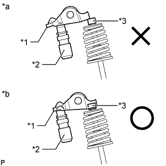
Text in Illustration *1 No. 1 Valve Rocker Arm Sub-assembly *2 Valve Lash Adjuster Assembly *3 Valve Stem Cap *a INCORRECT *b CORRECT Install the 16 No. 1 valve rocker arm sub-assemblies as shown in the illustration.
Note
Install the valve stem cap, valve lash adjuster assembly and No. 1 valve rocker arm sub-assembly to the same places they were removed from.
-
-
INSTALL CAMSHAFTS
Tech Tips
Perform "Inspection After Repairs" after replacing the camshaft or No. 2 camshaft Click here.
-
Apply clean engine oil to the camshaft cams and cylinder head journals.
-
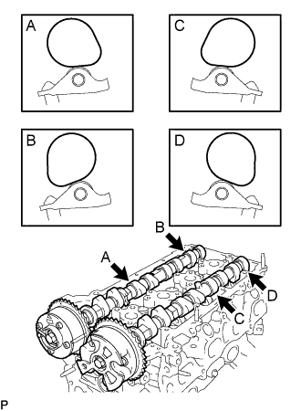
Position the camshaft and No. 2 camshaft as shown in the illustration.
-
Text in Illustration *1 No. 1 Valve Rocker Arm Sub-assembly *2 Valve Lash Adjuster Assembly *3 Valve Stem Cap *a INCORRECT *b CORRECT Make sure that the No. 1 valve rocker arm sub-assemblies are installed as shown in the illustration.
-
-
INSTALL CAMSHAFT BEARING CAP
-
Temporarily install the No. 1 camshaft bearing cap.
-
Confirm the location for each No. 2 camshaft bearing cap and install each one to the proper location.
-
Uniformly temporarily install the 20 bolts while keeping the camshaft level.
-
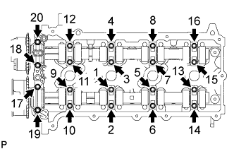
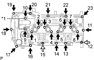
Tighten the 20 bolts in the order shown in the illustration.
- Torque:
- 16 N*m { 158 kgf*cm, 11 ft.*lbf }
-
-
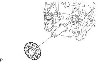
INSTALL CRANKSHAFT TIMING GEAR OR SPROCKET
-
Install the crankshaft timing gear or sprocket as shown in the illustration.
-
-
INSTALL NO. 1 CHAIN VIBRATION DAMPER
-
Install the No. 1 chain vibration damper with the bolt and nut.
- Torque:
- for bolt
- 21 N*m { 214 kgf*cm, 15 ft.*lbf }
- for nut
- 18 N*m { 184 kgf*cm, 13 ft.*lbf }
-
Remove the pin from the No. 2 chain tensioner assembly and release the plunger.
-
-
INSTALL CHAIN SUB-ASSEMBLY
-
Text in Illustration *1 Key *a Timing Mark *b Mark Plate (Pink) *c Mark Plate (Yellow) *d Approximately 13° *e Approximately 30° As shown in the illustration, install the chain sub-assembly to the camshaft timing exhaust gear assembly and camshaft timing gear assembly with the mark plates aligned with the timing marks on the camshaft timing exhaust gear assembly and camshaft timing gear assembly.
Tech Tips
-
The camshaft mark plate is pink.
-
The crankshaft mark plate is yellow.
-
-
Use a rope to tie the chain sub-assembly of the crankshaft timing gear or sprocket. Tie the rope near the crankshaft timing gear or sprocket.
Note
After the chain tensioner has been installed, the rope must be removed.
Tech Tips
The rope is tied so that the chain sub-assembly will not jump a tooth.
-
-
INSTALL CHAIN TENSIONER SLIPPER
-
Install the chain tensioner slipper with the bolt.
- Torque:
- 21 N*m { 214 kgf*cm, 15 ft.*lbf }
-
-
INSTALL NO. 1 CHAIN TENSIONER ASSEMBLY
-
Install a new gasket and the No. 1 chain tensioner assembly with the bolt and nut.
- Torque:
- 10 N*m { 102 kgf*cm, 7 ft.*lbf }
-
Text in Illustration *1 Plunger *a Stopper Plate *b Hexagon Wrench Move the stopper plate upward to release the lock, and push the plunger deep into the tensioner.
-
Move the stopper plate downward to set the lock, and insert a hexagon wrench into the stopper plate hole.
-
-
INSTALL TIMING CHAIN GUIDE
-
Text in Illustration *1 O-ring Install a new O-ring and the timing chain guide with the 2 bolts.
- Torque:
- 10 N*m { 102 kgf*cm, 7 ft.*lbf }
-
-
CHECK NO. 1 CYLINDER TO TDC/COMPRESSION
-
Check that the No. 1 cylinder is set to TDC/compression.
-
Text in Illustration *1 Key *a Timing Mark *b Approximately 13° *c Approximately 30° Rotate the crankshaft two full rotations, and then check that all timing marks are in the position shown in the illustration.
If the timing marks do not match, set the chain sub-assembly again.
-
-
-
INSTALL CYLINDER HEAD COVER CONNECTOR SUB-ASSEMBLY
-
Install a new No. 2 camshaft bearing cap oil hole gasket and 3 new No. 3 camshaft bearing cap oil hole gaskets to the camshaft bearing cap.
-
Install the cylinder head cover connector sub-assembly with the 2 bolts.
- Torque:
- 10 N*m { 102 kgf*cm, 7 ft.*lbf }
-
-
INSTALL TIMING CHAIN CASE OIL SEAL
-
Using SST and a hammer, tap in a new timing chain case oil seal until its surface is flush with the edge of the timing chain or belt cover sub-assembly.
- SST
- 09223-75010
- 09950-70010 ( 09951-07100 )
Note
-
Keep the lip free from foreign matter.
-
Do not tap the oil seal at an angle.
-
Apply MP grease to the lip of the timing chain case oil seal.
-
-
INSTALL ENGINE WATER PUMP ASSEMBLY
-
Install a new gasket and the engine water pump assembly with the 8 bolts.
- Torque:
- 8.9 N*m { 91 kgf*cm, 79 in.*lbf }
-
-
INSTALL TIMING CHAIN OR BELT COVER SUB-ASSEMBLY
-
Remove any old packing (FIPG material) and be careful not to drop any oil on the contact surfaces of the timing chain or belt cover sub-assembly, cylinder head sub-assembly and cylinder block sub-assembly.
-
Install 3 new O-rings to the timing chain or belt cover sub-assembly.
-
Align the width of the joint portion of the oil pump drive rotor and the crankshaft timing gear, and then install the timing chain or belt cover sub-assembly.
-
Apply seal packing as shown in the illustration.
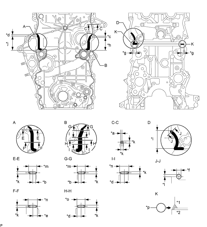
Text in Illustration *1 Cylinder Head Sub-Assembly *2 Cylinder Block Sub-assembly *a 2.0 mm (0.0787 in.) *b 2.5 mm (0.0984 in.) *c 5.0 mm (0.197 in.) *d 6.0 mm (0.236 in.) *e 7.0 mm (0.276 in.) *f 8.0 mm (0.315 in.) or more *g 20 mm (0.787 in.) *h 54 mm (2.13 in.) *i 56.5 mm (2.22 in.) *j 58 mm (2.28 in.) *k 2.5 to 4.0 mm (0.0984 to 0.157 in.) *l 5.0 to 6.0 mm (0.197 to 0.236 in.) *m 9.0 to 13 mm (0.354 to 0.512 in.) *n 10 to 14 mm (0.394 to 0.551 in.) *o 12 to 16 mm (0.472 to 0.630 in.) *p Seal Packing Seal packing Toyota Genuine Seal Packing Black, Three Bond 1207B or equivalent Note
-
When the contact surfaces are wet, wipe them with an oil-free cloth before applying seal packing.
-
Install the timing chain or belt cover sub-assembly within 3 minutes and tighten the bolts within 15 minutes after applying seal packing.
-
Do not add the engine oil for at least 4 hours after the installation.
-
Do not start the engine for at least 4 hours after the installation.
-
-
w/o Air Conditioning System:
Install the timing chain or belt cover sub-assembly with the 18 bolts and nut, and tighten the 18 bolts and nut in the sequence shown in the illustration.
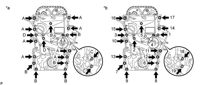
Text in Illustration *a Types of nut and bolt *b Tightening Order Bolt 
Nut - Torque:
- for Bolt A
- 57 N*m { 581 kgf*cm, 42 ft.*lbf }
- for Bolt B and Nut
- 23 N*m { 235 kgf*cm, 17 ft.*lbf }
- for Bolt C
- 21 N*m { 214 kgf*cm, 15 ft.*lbf }
- for Bolt D
- 25 N*m { 255 kgf*cm, 18 ft.*lbf }
Bolt Length Item Length Thread Diameter Bolt A 75 mm (2.95 in.) 10 mm (0.394 in.) Bolt B 75 mm (2.95 in.) 8.0 mm (0.315 in.) Bolt C 40 mm (1.57 in.) 8.0 mm (0.315 in.) Bolt D 90 mm (3.54 in.) 8.0 mm (0.315 in.) -
w/ Air Conditioning System:
Install the timing chain or belt cover sub-assembly with the 16 bolts and nut, and tighten the 16 bolts and nut in the sequence shown in the illustration.
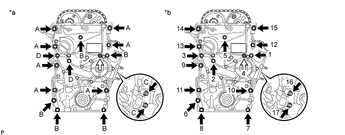
Text in Illustration *a Types of nut and bolt *b Tightening Order Bolt Nut - Torque:
- for Bolt A
- 57 N*m { 581 kgf*cm, 42 ft.*lbf }
- for Bolt B and Nut
- 23 N*m { 235 kgf*cm, 17 ft.*lbf }
- for Bolt C
- 21 N*m { 214 kgf*cm, 15 ft.*lbf }
- for Bolt D
- 25 N*m { 255 kgf*cm, 18 ft.*lbf }
Bolt Length Item Length Thread Diameter Bolt A 75 mm (2.95 in.) 10 mm (0.394 in.) Bolt B 75 mm (2.95 in.) 8.0 mm (0.315 in.) Bolt C 40 mm (1.57 in.) 8.0 mm (0.315 in.) Bolt D 90 mm (3.54 in.) 8.0 mm (0.315 in.) -
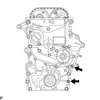
w/ Air Conditioning System:
Remove the seal packing from the 2 bolt holes for the No. 1 compressor mounting bracket.
Note
Do not use any cleaners to remove the seal packing.
-
-
INSTALL OIL STRAINER SUB-ASSEMBLY
-
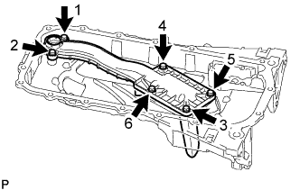
Install the oil strainer sub-assembly with the 6 bolts, and tighten the 6 bolts in the sequence shown in the illustration.
- Torque:
- 10 N*m { 102 kgf*cm, 7 ft.*lbf }
-
-
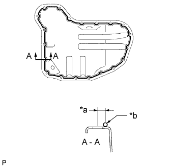
INSTALL OIL PAN SUB-ASSEMBLY
-
Install the stud bolt.
-
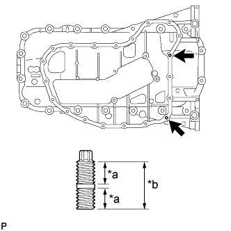
Text in Illustration *a 9.0 mm (0.354 in.) *b 19.0 mm (0.748 in.) Using an E6 "torx" socket wrench, install the stud bolts.
- Torque:
- 3.0 N*m { 31 kgf*cm, 27 in.*lbf }
-
-
Remove any old packing (FIPG material) and be careful not to drop any oil on the contact surfaces of the cylinder block sub-assembly and oil pan sub-assembly.
-
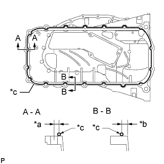
Text in Illustration *a 8.0 mm (0.315 in.) *b 6.5 mm (0.256 in.) *c Seal Packing Apply seal packing as shown in the illustration.
Seal packing Toyota Genuine Seal Packing Black, Three Bond 1207B or equivalent Standard seal diameter 2.0 to 3.0 mm (0.0787 to 0.118 in.) Note
-
Install the oil pan sub-assembly within 3 minutes and tighten the bolts within 15 minutes after applying seal packing.
-
Do not add the engine oil for at least 4 hours after the installation.
-
Do not start the engine for at least 4 hours after the installation.
-
-
Install a new gasket to the oil strainer sub-assembly.
-
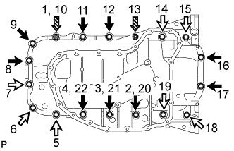
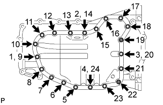
Install the oil pan sub-assembly with the 16 bolts and 2 nuts, and tighten the 16 bolts and 2 nuts in the sequence shown in the illustration.
- Torque:
- 26 N*m { 265 kgf*cm, 19 ft.*lbf }
Bolt Length Item Length Bolt A 20 mm (0.787 in.) Bolt B 40 mm (1.57 in.) Text in Illustration Bolt A Bolt B 
Nut
-
-
INSTALL NO. 2 OIL PAN SUB-ASSEMBLY
-
Remove any old packing (FIPG material) and be careful not to drop any oil on the contact surfaces of the oil pan sub-assembly and No. 2 oil pan sub-assembly.
-
Text in Illustration *a 6.0 mm (0.236 in.) *b Seal Packing Apply seal packing as shown in the illustration.
Seal packing Toyota Genuine Seal Packing Black, Three Bond 1207B or equivalent Standard seal diameter 3.0 to 4.0 mm (0.118 to 0.157 in.) Note
-
Install the No. 2 oil pan sub-assembly within 3 minutes and tighten the bolts within 15 minutes after applying seal packing.
-
Do not add the engine oil for at least 4 hours after the installation.
-
Do not start the engine for at least 4 hours after the installation.
-
-
Install the No. 2 oil pan sub-assembly with the 18 bolts and 2 nuts, and tighten the 18 bolts and 2 nuts in the sequence shown in the illustration.
- Torque:
- 9.0 N*m { 92 kgf*cm, 80 in.*lbf }
-
Install a new gasket and the oil pan drain plug.
- Torque:
- 38 N*m { 382 kgf*cm, 28 ft.*lbf }
-
-
INSTALL CRANKSHAFT PULLEY
-
Align the key groove of the crankshaft pulley with the crankshaft pulley reset key and install the crankshaft pulley.
-
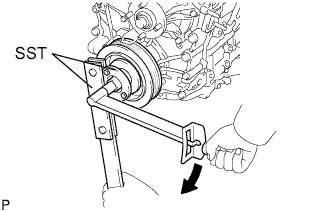
Using SST, hold the crankshaft pulley in place and tighten a new crankshaft pulley set bolt.
- SST
- 09213-54015 ( 91651-60855 )
- 09330-00021
- Torque:
- 260 N*m { 2651 kgf*cm, 192 ft.*lbf }
Note
Do not reuse the crankshaft pulley set bolt.
-
-
INSTALL NO. 1 VENTILATION CONNECTOR
-
Install the No. 1 ventilation connector to the cylinder head cover sub-assembly with the 2 bolts.
- Torque:
- 9.0 N*m { 92 kgf*cm, 80 in.*lbf }
-
-
INSTALL CYLINDER HEAD COVER SUB-ASSEMBLY
-
Remove any old packing (FIPG material) and be careful not to drop any oil on the contact surfaces of the cylinder head cover sub-assembly and cylinder head sub-assembly.
-
Apply seal packing as shown in the illustration.
Text in Illustration Seal Packing Application Area Seal packing Toyota Genuine Seal Packing Black, Three Bond 1207B or equivalent Standard seal diameter 4.0 mm (0.157 in.) Note
-
Install the cylinder head cover sub-assembly within 3 minutes and tighten the bolts within 15 minutes after applying seal packing.
-
Do not add the engine oil for at least 4 hours after the installation.
-
Do not start the engine for at least 4 hours after the installation.
-
-
Install a new No. 1 camshaft bearing cap oil hole gasket to the cylinder head cover spacer.
-
Install a new gasket to the cylinder head cover sub-assembly.
-
Text in Illustration *1 Plate Washer and Seal Washer Bolt Nut Install the cylinder head cover sub-assembly, 2 plate washers and 2 seal washers with the 21 bolts and 2 nuts, and tighten the 21 bolts and 2 nuts in the sequence shown in the illustration.
- Torque:
- 9.0 N*m { 92 kgf*cm, 80 in.*lbf }
Note
Make sure that the metal face of the seal washer is facing upward.
-
Connect the PCV hose to the PCV valve sub-assembly and slide the clip to secure the hose.
-
-
INSTALL CAMSHAFT TIMING OIL CONTROL VALVE ASSEMBLY
-
for Intake Side:
-
Apply a light coat of engine oil to the a new O-ring, and install it to the camshaft timing oil switching valve assembly.
Note
Do not damage the O-ring when installing.
Tech Tips
An O-ring is already installed in a new camshaft timing oil switching valve assembly. So, the O-ring only needs to be coated with engine oil when the assembly is replaced with a new one.
-
Install the camshaft timing oil switching valve assembly to the cylinder head sub-assembly with the bolt.
- Torque:
- 9.0 N*m { 92 kgf*cm, 80 in.*lbf }
Note
-
Replace with a new part if it is dropped or if it receives a strong impact.
-
Make sure that the O-ring is not cracked or jammed when installing.
-
Connect the camshaft timing oil switching valve connector.
-
-
for Exhaust Side:
-
Apply a light coat of engine oil to the a new O-ring, and install it to the camshaft timing oil switching valve assembly.
Note
Do not damage the O-ring when installing.
Tech Tips
An O-ring is already installed in a new camshaft timing oil switching valve assembly. So, the O-ring only needs to be coated with engine oil when the assembly is replaced with a new one.
-
Install the camshaft timing oil switching valve assembly to the cylinder head cover sub-assembly with the bolt.
- Torque:
- 9.0 N*m { 92 kgf*cm, 80 in.*lbf }
Note
-
Replace with a new part if it is dropped or if it receives a strong impact.
-
Make sure that the O-ring is not cracked or jammed when installing.
-
Connect the camshaft timing oil switching valve connector.
-
-
-
INSTALL CRANKSHAFT POSITION SENSOR
-
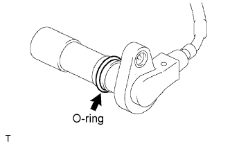
Apply a light coat of engine oil to the O-ring of the crankshaft position sensor.
-
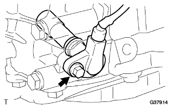
Install the crankshaft position sensor with the bolt.
- Torque:
- 8.5 N*m { 87 kgf*cm, 75 in.*lbf }
Note
Make sure that the O-ring is not cracked or jammed when installing.
-
Connect the crankshaft position sensor connector and the 2 wire harness clamps.
-
-
INSTALL CAMSHAFT POSITION SENSOR
-
for Intake Side:
-
Apply a light coat of engine oil to the O-ring of the camshaft position sensor.
-
Install the camshaft position sensor with the bolt.
- Torque:
- 9.0 N*m { 92 kgf*cm, 80 in.*lbf }
Note
-
When reusing the camshaft position sensor, inspect the O-ring.
-
Make sure that the O-ring is not cracked or jammed when installing the camshaft position sensor.
-
Connect the camshaft position sensor connector.
-
-
for Exhaust Side:
-
Apply a light coat of engine oil to the O-ring of the camshaft position sensor.
-
Install the camshaft position sensor with the bolt.
- Torque:
- 9.0 N*m { 92 kgf*cm, 80 in.*lbf }
Note
-
When reusing the camshaft position sensor, inspect the O-ring.
-
Make sure that the O-ring is not cracked or jammed when installing the camshaft position sensor.
-
Connect the camshaft position sensor connector.
-
-
-
INSTALL PCV VALVE SUB-ASSEMBLY
-
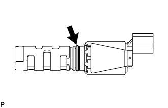
Apply a light coat of engine oil to the O-ring.
-
Install the ventilation valve.
- Torque:
- 5.0 N*m { 51 kgf*cm, 44 in.*lbf }
Tech Tips
When reusing the ventilation valve, inspect the O-ring.
If the O-ring has scratches or cuts, replace the ventilation valve.
-
Connect the ventilation hose to the ventilation valve.
-
Secure the hose with the clamp.
-
-
INSTALL OIL FILLER CAP SUB-ASSEMBLY