ECD SYSTEM, Diagnostic DTC:35
| DTC Code | DTC Name |
|---|---|
| 35 | Manifold Absolute Pressure / Barometric Pressure Circuit Malfunction |
DESCRIPTION
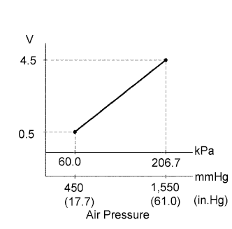
The manifold absolute pressure sensor generates voltage by the vacuum value as shown in the illustration. The voltage of the manifold absolute pressure sensor is one of the factors used to determine the injection volume and injection timing.
| DTC No. | DTC Detection Condition | Trouble Area |
|---|---|---|
| 35 | Open or short in manifold absolute pressure sensor circuit for 2 sec. or more |
|
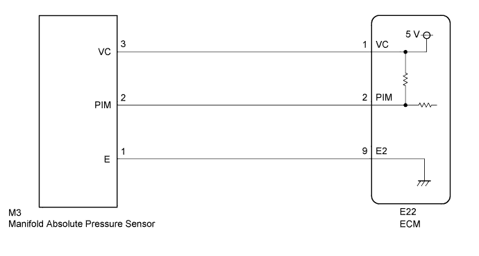
WIRING DIAGRAM
INSPECTION PROCEDURE
Tech Tips
-
If DTCs that are related to different systems are output simultaneously while terminal E2 is used as a ground terminal, terminal E2 may be open.
-
Read freeze frame data using the intelligent tester. The ECM records vehicle and driving condition information as freeze frame data the moment a DTC is stored. When troubleshooting, freeze frame data can be helpful in determining whether the vehicle was running or stopped, whether the engine was warmed up or not, whether the air-fuel ratio was lean or rich, as well as other data recorded at the time of a malfunction.
When using intelligent tester:
PROCEDURE
-
READ VALUE USING INTELLIGENT TESTER (INTAKE MANIFOLD PRESSURE)
-
Connect the intelligent tester to the DLC3.
-
Turn the ignition switch ON.
-
Enter the following menus: Powertrain / Engine and ECT / Data List / PIM.
OK The same as atmospheric pressure. Tech Tips
When DTC 35 is present, the type of malfunction can be determined based on the manifold absolute pressure (see below).
Intake Manifold Pressure (kPa) Malfunction Approx. 0
-
Short in PIM circuit
192 or more
-
Open or short in VC circuit
-
Open in PIM circuit
-
Open in E2 circuit
-
NG 
INSPECT MANIFOLD ABSOLUTE PRESSURE SENSOR Click here
OK 
-
-
CHECK CONNECTION OF VACUUM HOSE
-
Check that the vacuum hose is securely connected and that there are no leaks from the connection.
OK The vacuum hose is securely connected and there are no leaks from the connection.
NG 
REPAIR OR REPLACE VACUUM HOSE
OK 
CHECK FOR INTERMITTENT PROBLEMS
-
-
INSPECT MANIFOLD ABSOLUTE PRESSURE SENSOR
-
Inspect the manifold absolute pressure sensor Click here.
NG
REPLACE MANIFOLD ABSOLUTE PRESSURE SENSOR
OK
-
-
CHECK ECM (VC VOLTAGE)
-
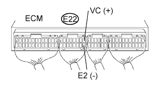
Turn the ignition switch ON.
-
Measure the voltage of the ECM connector.
Standard voltage Tester Connection Specified Condition E22-1 (VC) - E22-9 (E2) 4.5 to 5.5 V
NG
REPLACE ECM
OK
-
-
CHECK ECM (PIM VOLTAGE)
-
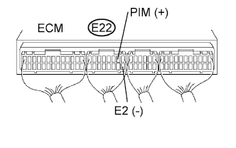
Turn the ignition switch ON.
-
Measure the voltage of the ECM connector.
Standard voltage Tester Connection Specified Condition E22-2 (PIM) - E22-9 (E2) 1.0 to 2.2 V
OK
REPLACE ECM
NG
-
-
CHECK WIRE HARNESS (ECM - MANIFOLD ABSOLUTE PRESSURE SENSOR)
-
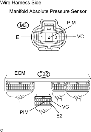
Disconnect the M3 manifold absolute pressure sensor connector.
-
Disconnect the E22 ECM connector.
-
Measure the resistance of the wire harness side connectors.
Standard resistance Tester Connection Specified Condition M3-3 (VC) - E22-1 (VC) Below 1 Ω M3-2 (PIM) - E22-2 (PIM) Below 1 Ω M3-1 (E) - E22-9 (E2) Below 1 Ω E22-1 (VC) - E22-2 (PIM) 10 kΩ or higher E22-1 (VC) - E22-9 (E2) 10 kΩ or higher E22-2 (PIM) - E22-9 (E2) 10 kΩ or higher
NG
REPAIR OR REPLACE HARNESS AND CONNECTOR
OK
CHECK FOR INTERMITTENT PROBLEMS
-
When not using intelligent tester:
PROCEDURE
-
INSPECT MANIFOLD ABSOLUTE PRESSURE SENSOR
-
Inspect the manifold absolute pressure sensor Click here.
NG
REPLACE MANIFOLD ABSOLUTE PRESSURE SENSOR
OK
-
-
CHECK ECM (VC VOLTAGE)
-
Turn the ignition switch ON.
-
Measure the voltage of the ECM connector.
Standard voltage Tester Connection Specified Condition E22-1 (VC) - E22-9 (E2) 4.5 to 5.5 V
NG
REPLACE ECM
OK
-
-
CHECK ECM (PIM VOLTAGE)
-
Turn the ignition switch ON.
-
Measure the voltage of the ECM connector.
Standard voltage Tester Connection Specified Condition E22-2 (PIM) - E22-9 (E2) 1.0 to 2.2 V
OK
REPLACE ECM
NG
-
-
CHECK WIRE HARNESS (ECM - MANIFOLD ABSOLUTE PRESSURE SENSOR)
-
Disconnect the M3 manifold absolute pressure sensor connector.
-
Disconnect the E22 ECM connector.
-
Measure the resistance of the wire harness side connectors.
Standard resistance Tester Connection Specified Condition M3-3 (VC) - E22-1 (VC) Below 1 Ω M3-2 (PIM) - E22-2 (PIM) Below 1 Ω M3-1 (E) - E22-9 (E2) Below 1 Ω E22-1 (VC) - E22-2 (PIM) 10 kΩ or higher E22-1 (VC) - E22-9 (E2) 10 kΩ or higher E22-2 (PIM) - E22-9 (E2) 10 kΩ or higher
NG
REPAIR OR REPLACE HARNESS AND CONNECTOR
OK
CHECK FOR INTERMITTENT PROBLEMS
-