WIPER AND WASHER SYSTEM(w/ Rain Sensor) Washer Signal Circuit
| DTC Code | DTC Name |
|---|---|
| Washer Signal Circuit |
DESCRIPTION
The headlight cleaner control relay receives the windshield washer operation signal.
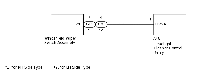
WIRING DIAGRAM
PROCEDURE
CHECK OPERATION
Check the operation of the front wiper and washer system.
Result
Proceed to
Front wiper and washer system operates normally
Front wiper and washer system does not operate
Front wiper and washer system does not operate GO TO PROBLEM SYMPTOMS TABLE
CHECK HEADLIGHT CLEANER CONTROL RELAY
-
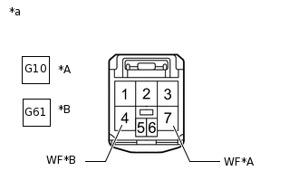
*A
for RH Side Type
*B
for LH Side Type
*a
Front view of wire harness connector
(to Windshield Washer Motor and Pump Assembly)
Disconnect the windshield wiper switch assembly connector.
Measure the voltage according to the value(s) in the table below.
Standard Voltage
Table 1. for RH Side Type Tester Connection
Switch Condition
Specified Condition
G10-7 (WF) - Body ground
Ignition switch ON
11 to 14 V
Ignition switch off
Below 1 V
Table 2. for LH Side Type Tester Connection
Switch Condition
Specified Condition
G61-4 (WF) - Body ground
Ignition switch ON
11 to 14 V
Ignition switch off
Below 1 V
Result
Proceed to
OK
NG
-
CHECK HARNESS AND CONNECTOR (HEADLIGHT CLEANER CONTROL RELAY - WINDSHIELD WIPER SWITCH ASSEMBLY)
Disconnect the A48 headlight cleaner control relay connector.
Disconnect the G10*1 or G61*2 windshield wiper switch assembly connector.
*1: for RH Side Type
*2: for LH Side Type
Measure the resistance according to the value(s) in the table below.
Standard Resistance
Table 3. for RH Side Type Tester Connection
Condition
Specified Condition
A48-5 (FRWA) - G10-7 (WF)
Always
Below 1 Ω
A48-5 (FRWA) - Body ground
Always
10 kΩ or higher
Table 4. for LH Side Type Tester Connection
Condition
Specified Condition
A48-5 (FRWA) - G61-4 (WF)
Always
Below 1 Ω
A48-5 (FRWA) - Body ground
Always
10 kΩ or higher
Result
Proceed to
OK
NG
NG REPAIR OR REPLACE HARNESS OR CONNECTOR