FRONT SENSOR ADJUSTMENT
CAUTION / NOTICE / HINT
The pre-collision city sensor uses lasers to detect preceding vehicles. The pre-collision city sensor is classified as a Class 1M laser product according to the IEC 60825-1 standard. These lasers are not harmful to the naked eye. However, it is necessary to observe the following precautions. Failure to do so may result in severe visual impairment, or at worst, loss of eyesight.
To avoid hazardous laser radiation exposure, never attempt to disassemble the pre-collision city sensor or perform maintenance procedures that are not described in the repair manual. When disassembled, the pre-collision city sensor is classified as a Class 3B laser product according to the IEC 60825-1 standard and poses an eye injury risk.
Do not look into the pre-collision city sensor using a magnifying glass, microscope or other optical instrument from a distance of 100 mm (3.94 in.) or less.
Be careful of burns and injuries, as the pre-collision city sensor reaches high temperatures.
When replacing the windshield glass of a vehicle equipped with a pre-collision city sensor, make sure to use a Toyota genuine part. If a non-Toyota genuine part is used, the pre-collision city sensor may not be able to be installed due to a missing bracket or the pre-collision system may not operate properly due to a difference in the transmissivity of the windshield glass or the shape of the black ceramic border.
Pre-collision city sensor optical learning can be performed by either using One Time Recognition or Sequential Recognition.
One Time Recognition is an optical learning method in which 3 targets are recognized simultaneously at 1 position directly in front of the front bumper.
Sequential Recognition is an optical learning method in which 1 target is recognized sequentially at 3 positions 3 m from the pre-collision city sensor.
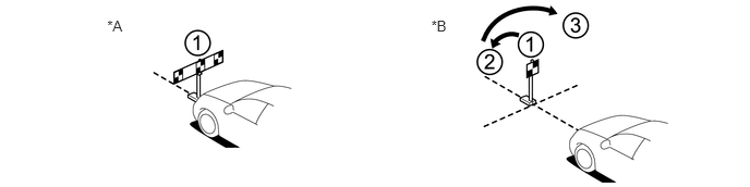
*A |
for One Time Recognition |
*B |
for Sequential Recognition |
Recognition Method |
Number of Targets |
Target Position |
Number of Times Target Recognition Performed |
|---|---|---|---|
One Time Recognition |
3 |
1 (In front of front bumper) |
1 |
Sequential Recognition |
1 |
3 (3 m from the pre-collision city sensor) |
3 |
PROCEDURE
PREPARATION FOR PRE-COLLISION CITY SENSOR OPTICAL AXIS LEARNING (for One Time Recognition)
-
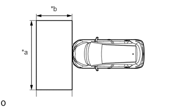
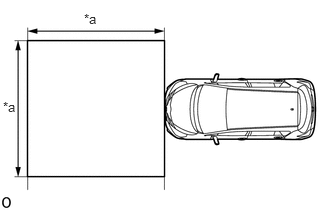
Park the vehicle on a level surface.
Table 2. Text in Illustration *a
2 m (6.56 ft.)
*b
1 m (3.28 ft.)
Note:Make sure there are no black and white patterned objects in front of the vehicle.
Perform adjustments indoors to avoid the possible effects of sunlight.
Perform the following procedures in an area with no wind.
Perform the following procedures in a bright area.
Tip:Make sure that the area shown in the illustration in front of the vehicle is free of reflective or shiny objects.
Check that the headlights are turned off.
Adjust the tire inflation pressure to the specified pressure (Click here).
Clean the windshield glass.
-
PERFORM PRE-COLLISION CITY SENSOR CAMERA AXIS LEARNING (for One Time Recognition)
Create a target sheet.
Print 3 copies of the illustration.

-
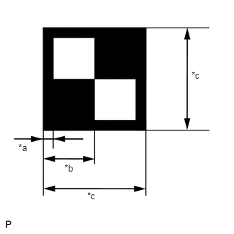
Check that the dimensions are within the values shown in the illustration.
Table 3. Text in Illustration *a
12 mm (0.472 in.)
*b
60 mm (2.36 in.)
*c
120 mm (4.72 in.)
Note:Make sure that the black areas of the target sheet are not glossy.
Make sure that the borders of the black and white areas on the target sheet are straight, and are not warped or blurry.
Tip:If the dimensions of the created target sheet are not within +/- 5 mm (0.197 in.) of the specified values, adjust the printer settings and reprint the target sheet so that the dimensions are as specified.
Attach the target sheet.
Prepare a piece of cardboard with the following dimensions.
Draw lines on the cardboard as shown in the illustration.
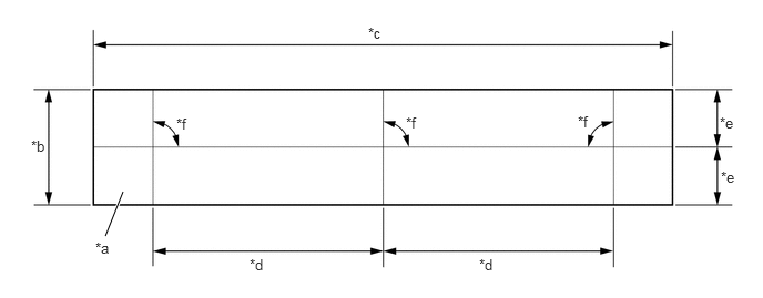
Table 4. Text in Illustration *a
Cardboard
*b
130 mm (5.12 in.) or more
*c
730 mm (2.39 ft.) or more
*d
297 mm (11.7 in.)
*e
65 mm (2.56 in.) or more
*f
90°
Place the 3 target sheets on the cardboard with the black area of each at the top right and align the boarders of the black and white areas with the lines as shown in the illustration.
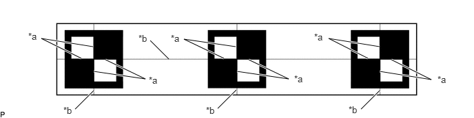
Table 5. Text in Illustration *a
Boarder of Black and White Area
*b
Line
Securely attach the target sheets to the cardboard using double-sided tape.
Note:Do not attach reflective materials, such as clear adhesive tape, to the target sheet surface as this may affect target recognition.
Hang a weight with a pointed tip from the top center of the target sheet as shown in the illustration.
09870-60000
09870-60010
09870-60020
-
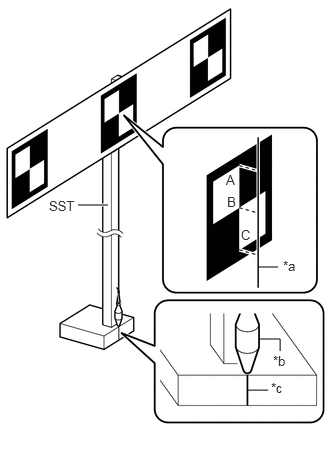
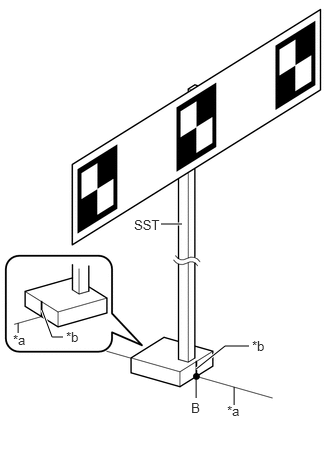
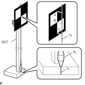
Using double-sided tape, attach the target sheet to the reflector so that the weight is aligned with the mark-off line of SST.
Table 6. Text in Illustration *a
String
*b
Weight
*c
Mark-off Line
Note:Make sure that the points (A), (B) and (C) of the target sheet are aligned with the string.
As SST may fall forward, make sure to place a weight on the base of SST.
-
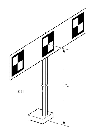
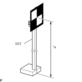
Move the reflector up or down so that the center of the target sheet is at the height shown in the illustration, and secure the reflector in place.
Table 7. Text in Illustration *a
1270 mm (50 in.)
Note:If the center of the target sheet is not within +/- 6 mm (0.236 in.) of the height specified, adjust the position of the reflector so that the height is as specified.
Measure the target placement point.
Note:Make sure the background behind the target has no patterns.
Make sure that there are no reflective or shiny objects around the target.
Make sure that the shadow of the target is not cast onto a wall as this may cause a target recognition error.
Hang a weight with a pointed tip from the center of the rear emblem, and mark the rear center point of the vehicle (point A) on the ground.
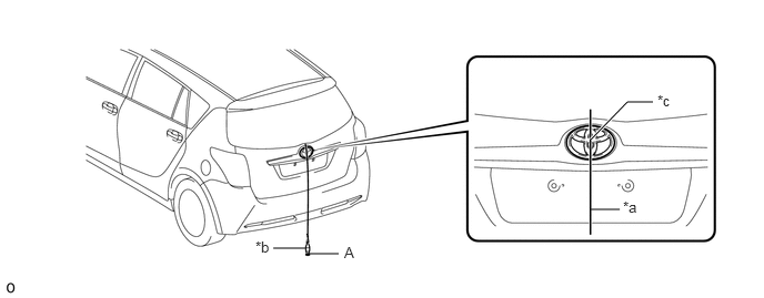
Table 8. Text in Illustration *a
String
*b
Weight
*c
Center
-
-
Tip:Lightly flick the string with your fingers several times to confirm that the string is perpendicular to the ground.
Hang a weight with a pointed tip from the center of the front emblem, and mark the front center point of the vehicle (point B) on the ground (placement position).
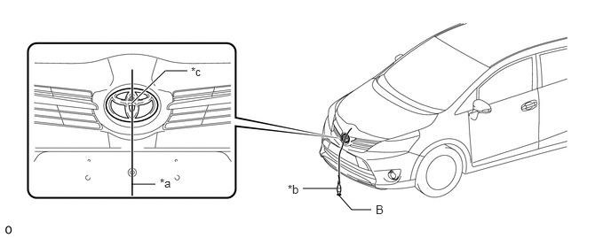
Table 9. Text in Illustration *a
String
*b
Weight
*c
Center
-
-
Tip:Lightly flick the string with your fingers several times to confirm that the string is perpendicular to the ground.
Using tape and a string, create a line that connects point B to point A and extends at least 200 mm (7.87 in.) beyond the front center point of the vehicle (target position line).
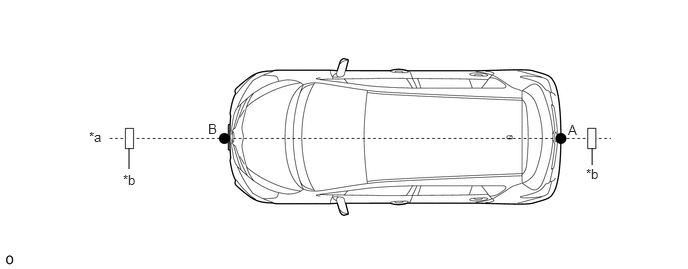
Table 10. Text in Illustration *a
String
*b
Tape
Tip:Make sure the string is taut when securing it with tape.
Lightly flick the string with your fingers several times to confirm that the string is aligned with point B.
Perform Recognition Camera/Target Position Memory.
CAUTION:Do not look into the pre-collision city sensor from a close distance.
Note:Close all of the doors.
Make sure that no one is inside the vehicle.
Do not lean on the vehicle.
Make sure that the headlights are turned off.
Connect the GTS to the DLC3.
Turn the ignition switch to ON.
Turn the GTS on.
Enter the following menus:
Chassis > PCS/LDA/RSA/LVN > Utility
According to the display on the GTS, press "Next". *1
Confirm the conditions displayed on the screen, and then press "Next".
Input "1423 mm (56.02 in.)" for the height of the recognition camera.
Input "21 mm (0.83 in.)" for the lateral position of the recognition camera, then press "Next".
Input "0 deg" for the yaw angle of the recognition camera.
Input "-2.24 deg" for the pitch angle of the recognition camera, and then press "Next".
Input "1270 mm (50 in.)" for the height of the target.
Input "1653 mm (65.08 in.)" for the distance between the recognition camera and target, and then press "Next".
Input "297 mm (11.69 in.)" for the distance between the targets.
Input "120 mm (4.72 in.)" for the target size, and then press "Next".
Input "1785 mm (70.28 in.)" for the width of the vehicle.
Input "727 mm (28.62 in.)" for the distance between the recognition camera and front tires, and then press "Next".
Input "0 deg" for the pitch offset angle.
Input "0 mm (0 in.)" for the distance between the recognition camera and the radar, and then press "Next".
If "Recognition Camera/Target Position Memory has failed." is displayed on the GTS screen, confirm the conditions displayed on the screen, then press "Yes" and repeat the procedure from *1.
Press "Exit" to exit the Recognition Camera/Target Position Memory utility.
Perform Recognition Camera Axis Adjust (target positioning).
Note:If "Recognition Camera Axis Adjust has failed." is displayed on the screen, confirm the following conditions, turn the ignition switch off and then to ON, and repeat the procedure from *1.
Make sure that the height of the target is correct.
Make sure that the target placement positions are correct.
Make sure that the orientation of the target sheet is correct (black area positioned at the top right).
Make sure that the surrounding area is sufficiently bright.
Make sure that there are no reflective or shiny objects around the target.
Make sure that there are no black and white patterned objects around the target or on a wall near the target.
Make sure that the shadow of the target is not cast onto a wall.
Make sure that the windshield glass is clean.
-
Position SST so that it is aligned with the target position line and the mark-off line is aligned with point B (placement position) as shown in the illustration.
09870-60000
09870-60010
09870-60020
Table 11. Text in Illustration *a
Target Placement Line
*b
Mark-off Line
Enter the following menus:
Chassis > PCS/LDA/RSA/LVN > Utility
According to the display on the GTS, press "Next". *1
Check that the values stored in the ECU are correct, and then press "Next".
Confirm the conditions displayed on the screen, and then press "Next".
Select "Batch recognition", and then press "Next".
Check that target is placed at point B (placement position), and then press "Next".
If "Failed to read axis adjustment data" is displayed, perform Recognition Camera/Target Position Memory, and repeat the procedure from *1.
Confirm the conditions displayed on the screen, and then press "Next".
Turn the ignition switch off.
Disconnect the GTS from the DLC3.
PREPARATION FOR PRE-COLLISION CITY SENSOR OPTICAL AXIS LEARNING (for Sequential Recognition)
-
Park the vehicle on a level surface.
Table 12. Text in Illustration *a
3 m (9.84 ft.)
Note:Make sure there are no black and white patterned objects in front of the vehicle.
Perform adjustments indoors to avoid the possible effects of sunlight.
Perform the following procedures in an area with no wind.
Perform the following procedures in a bright area.
Tip:Make sure that the area shown in the illustration in front of the vehicle is free of reflective or shiny objects.
Check that the headlights are turned off.
Adjust the tire inflation pressure to the specified pressure (Click here).
Clean the windshield glass.
-
PERFORM PRE-COLLISION CITY SENSOR CAMERA AXIS LEARNING (for Sequential Recognition)
Create a target sheet.
Print the illustration.

-
Check that the dimensions are within the values shown in the illustration.
Table 13. Text in Illustration *a
16 mm (0.63 in.)
*b
80 mm (3.15 in.)
*c
160 mm (6.29 in.)
Note:Make sure that the black areas of the target sheet are not glossy.
Make sure that the borders of the black and white areas on the target sheet are straight, and are not warped or blurry.
Tip:If the dimensions of the created target sheet are not within +/- 5 mm (0.197 in.) of the specified values, adjust the printer settings and reprint the target sheet so that the dimensions are as specified.
-
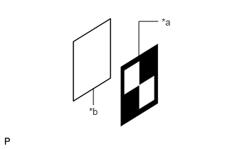
Attach the target sheet.
Table 14. Text in Illustration *a
Target Sheet
*b
Cardboard
Cut a piece of cardboard to the same size as the target sheet.
Place the target sheet on the cardboard with the black area at the top right as shown in the illustration, and securely attach the target sheet using double-sided tape.
Note:Do not attach reflective materials, such as clear adhesive tape, to the target sheet surface as this may affect target recognition.
-
Hang a weight with a pointed tip from the top center of the target sheet as shown in the illustration.
09870-60000
09870-60010
09870-60020
Table 15. Text in Illustration *a
String
*b
Weight
*c
Mark-off Line
Using double-sided tape, attach the target sheet to the reflector so that the weight is aligned with the mark-off line of SST.
Tip:Make sure that the points (A), (B) and (C) of the target sheet are aligned with the string.
-
Move the reflector up or down so that the center of the target sheet is at the height shown in the illustration, and secure the reflector in place.
09870-60000
09870-60010
09870-60020
Table 16. Text in Illustration *a
1270 mm (50 in.)
Note:If the center of the target sheet is not within +/- 6 mm (0.236 in.) of the height specified, adjust the position of the reflector so that the height is as specified.
Determine the target placement position.
Note:Make sure the background behind the target has no patterns.
Make sure that there are no reflective or shiny objects around the target.
Make sure that the shadow of the target is not cast onto a wall as this may cause a target recognition error.
Hang a weight with a pointed tip from the center of the rear emblem, and mark the rear center point of the vehicle (point A) on the ground.
Table 17. Text in Illustration *a
String
*b
Weight
*c
Center Point
-
-
Tip:Lightly flick the string with your fingers several times to confirm that the string is perpendicular to the ground.
Hang a weight with a pointed tip from the center of the vehicle front bumper (center of emblem). Mark the front center point of the vehicle (point B) on the ground.
Table 18. Text in Illustration *a
String
*b
Weight
*c
Center Point
-
-
Tip:Lightly flick the string with your fingers several times to confirm that the string is perpendicular with the floor.
Using tape and a string, create a line that connects point B to point A and extends at least 2300 mm (7.55 ft.) beyond the front center point of the vehicle.
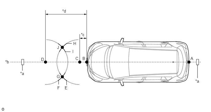
Table 19. Text in Illustration *a
Tape
*b
String
*c
547 mm (1.79 ft.)
*d
2147 mm (7.04 ft.)
Tip:Make sure the string is taut when securing it with tape.
Lightly flick the string with your fingers several times to confirm that the string is aligned with point B.
Mark point C at a position 547 mm (1.79 ft.) in front of point B.
Mark point D at a position 2147 mm (7.04 ft.) in front of point B.
Using a string, mark line E at a position 1000 mm (3.28 ft.) from point C.
Using a string, mark line H at a position 1000 mm (3.28 ft.) from point C.
Using a string, mark line F at a position 1000 mm (3.28 ft.) from point D.
Using a string, mark line I at a position 1000 mm (3.28 ft.) from point D.
Mark point G (placement point 2) at the point where line E and line F intersect.
Mark point J (placement point 3) at the point where line H and line I intersect.
Using tape and a string, create a line that connects point G and point J (target placement line).
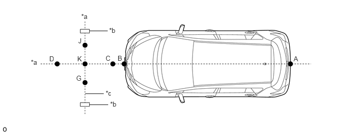
Table 20. Text in Illustration *a
String
*b
Tape
*c
Target Placement Line
-
-
Tip:Make sure the string is taut when securing it with tape.
Lightly flick the string with your fingers several times to confirm that the string is aligned with points G and J.
Mark point K (placement position 1) at the point the string connecting points C and D and the string connecting points G and J intersect.
Confirm that the distance between points K and G (placement positions 1 and 2), and K and J (placement positions 2 and 3) is 600 mm (23.62 in.).
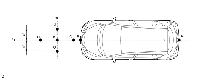
Table 21. Text in Illustration *a
String
*b
600 mm (23.62in.)
Note:If the distance between either pair of points is not within +/- 3 mm (0.118 in.) of the specified value, start over from marking of point A.
Perform Recognition Camera/Target Position Memory.
CAUTION:Do not look into the pre-collision city sensor from a close distance.
Note:Close all of the doors.
Make sure that no one is inside the vehicle.
Do not lean on the vehicle.
Make sure that the headlights are turned off.
Connect the GTS to the DLC3.
Turn the ignition switch to ON.
Turn the GTS on.
Enter the following menus:
Chassis > PCS/LDA/RSA/LVN> Utility
According to the display on the GTS, press "Next". *1
Confirm the conditions displayed on the screen, and then press "Next".
Input "1423 mm (56.02 in.)" for the height of the recognition camera.
Input "21 mm (0.83 in.)" for the lateral position of the recognition camera, then press "Next".
Input "0 deg" for the yaw angle of the recognition camera.
Input "-2.24 deg" for the pitch angle of the recognition camera, and then press "Next".
Input "1270 mm (50 in.)" for the height of the target.
Input "3000 mm (118.11 in.)" for the distance between the recognition camera and target, and then press "Next".
Input "600 mm (23.62 in.)" for the distance between the targets.
Input "160 mm (6.30 in.)" for the target size, and then press "Next".
Input "1785 mm (70.28 in.)" for the width of the vehicle.
Input "727 mm (28.62 in.)" for the distance between the recognition camera and front tires, and then press "Next".
Input "0 deg" for the pitch offset angle.
Input "0 mm (0 in.)" for the distance between the recognition camera and the radar, and then press "Next".
If "Recognition Camera/Target Position Memory has failed." is displayed on the GTS screen, confirm the conditions displayed on the screen, then press "Yes" and repeat the procedure from *1.
Press "Exit" to exit the Recognition Camera/Target Position Memory utility.
Perform Recognition Camera Axis Adjust (target positioning).
Note:If "Recognition Camera Axis Adjust has failed." is displayed on the screen, confirm the following conditions, turn the ignition switch off and then to ON, and repeat the procedure from *1.
Make sure that the height of the target is correct.
Make sure that the target placement positions are correct.
Make sure that the orientation of the target sheet is correct (black area positioned at the top right).
Make sure that the surrounding area is sufficiently bright.
Make sure that there are no reflective or shiny objects around the target.
Make sure that there are no black and white patterned objects around the target or on a wall near the target.
Make sure that the shadow of the target is not cast onto a wall.
Make sure that the windshield glass is clean.
-

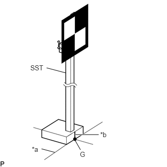
Position SST so that it is aligned with the target position line and the mark-off line is aligned with point K (placement position 1) as shown in the illustration.
09870-60000
09870-60010
09870-60020
Table 22. Text in Illustration *a
Target Placement Line
*b
Mark-off Line
Enter the following menus:
Chassis > PCS/LDA/RSA/LVN> Utility
According to the display on the GTS, press "Next". *1
Check that the values stored in the ECU are correct, and then press "Next".
Confirm the conditions displayed on the screen, and then press "Next".
Select "Sequential recognition", and then press "Next".
Check that target is placed at point K (placement position 1), and then press "Next".
-
Position SST so that it is aligned with the target position line and the mark-off line is aligned with point G (placement position 2) as shown in the illustration.
09870-60000
09870-60010
09870-60020
Table 23. Text in Illustration *a
Target Placement Line
*b
Mark-off Line
Note:Position SST and press "Next" within 3 minutes of the screen changing to the Recognition Camera Axis Adjust screen for point G (placement position 2).
-

Position SST so that it is aligned with the target position line and the mark-off line is aligned with point J (placement position 3) as shown in the illustration.
09870-60000
09870-60010
09870-60020
Table 24. Text in Illustration *a
Target Placement Line
*b
Mark-off Line
Note:Position SST and press "Next" within 3 minutes of the screen changing to the Recognition Camera Axis Adjust screen for point J (placement position 3).
If "Failed to read axis adjustment data" is displayed, perform Recognition Camera/Target Position Memory, and repeat the procedure from *1.
Confirm the conditions displayed on the screen, and then press "Next".
Turn the ignition switch off.
Disconnect the GTS from the DLC3.