BRAKE BOOSTER(for RHD) REMOVAL
CAUTION / NOTICE / HINT
The necessary procedures (adjustment, calibration, initialization, or registration) that must be performed after parts are removed, installed, or replaced during brake booster assembly removal/installation are shown below.
| Replaced Part or Performed Procedure | Necessary Procedure | Effect/Inoperative Function when Necessary Procedure not Performed | Link |
|---|---|---|---|
| Battery terminal is disconnected/reconnected | Drive the vehicle until stop and start control is permitted (approximately 5 to 60 minutes) | Stop and start system | |
| Memorize steering angle neutral point | LKA/LDA system | ||
| Parking support brake system* | |||
| Pre-collision system | |||
| Adaptive high beam system | |||
Lighting system (EXT) |
|||
| Initialize rear door sunshade system | Variable gear ratio steering system | ||
| Initialize power trunk lid system | Parking assist monitor system | ||
| Brake actuator assembly | Perform acceleration sensor (yaw rate sensor) zero point calibration and store system information |
|
Click here Click here
Note
Make sure to release vacuum from the brake booster assembly before removing the brake master cylinder sub-assembly from the brake booster assembly.
PROCEDURE
-
PRECAUTION
Note
After turning the engine switch off, waiting time may be required before disconnecting the cable from the negative (-) battery terminal. Therefore, make sure to read the disconnecting the cable from the negative (-) battery terminal notices before proceeding with work.
-
REMOVE BRAKE ACTUATOR ASSEMBLY WITH BRACKET
-
REMOVE VACUUM SENSOR ASSEMBLY
-
REMOVE VACUUM SENSOR GROMMET
-
REMOVE VACUUM WARNING SWITCH ASSEMBLY
-
REMOVE VACUUM WARNING SWITCH GROMMET
-
REMOVE BRAKE MASTER CYLINDER SUB-ASSEMBLY
-
REMOVE LOWER NO. 1 INSTRUMENT PANEL AIRBAG ASSEMBLY
-
REMOVE NO. 1 AIR DUCT SUB-ASSEMBLY
-
REMOVE NO. 1 HEATER TO REGISTER DUCT
-
REMOVE BRAKE PEDAL RETURN SPRING
-
REMOVE PUSH ROD PIN
-
REMOVE BRAKE BOOSTER ASSEMBLY
-
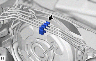
Disengage the clamp to separate the 4 brake lines.
Note
Do not kink or damage the brake lines.
-
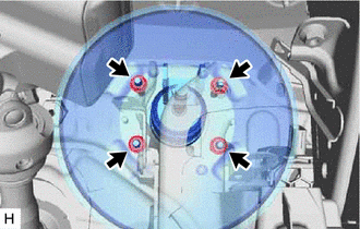
Remove the 4 nuts and brake booster assembly from the vehicle body.
Note
Do not apply excessive force to the brake lines.
-
-
REMOVE BRAKE BOOSTER GASKET
-
REMOVE BOOSTER BRACKET STOPPER RING
-
Remove the 2 brake booster stopper rings from the brake booster assembly.
-
-
REMOVE BRAKE BOOSTER BRACKET
-
REMOVE BRAKE BOOSTER GASKET
-
REMOVE BRAKE MASTER CYLINDER PUSH ROD CLEVIS
-
Loosen the clevis lock nut and remove the brake master cylinder push rod clevis and clevis lock nut from the brake booster assembly.
-
-
REMOVE BRAKE VACUUM CHECK VALVE ASSEMBLY
-
Remove the brake vacuum check valve assembly from the brake booster assembly.
-
Remove the check valve grommet from the brake booster assembly.
-