AIR CONDITIONING SYSTEM(for Manual Air Conditioning System) SYSTEM DESCRIPTION
GENERAL
The air conditioning system has the following controls.
Control
Outline
Manual Control
Damper positions and blower speed operate automatically according to the operation of switches such as the temperature control switch, blower switch, mode control switch and inlet control switch.
Compressor Control
Through the calculation of the target evaporator temperature based on various sensor signals, the air conditioning amplifier optimally controls discharge capacity by regulating the opening extent of the compressor solenoid valve.
Diagnosis
A Diagnostic Trouble Code (DTC) is stored in memory when the air conditioning amplifier assembly detects a problem with the air conditioning system.
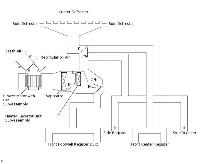
MODE POSITION AND DAMPER OPERATION
Mode Position and Damper Operation.
*a
Air also blows out of the side registers
*b
Air also blows out of the side registers and defrosters
Table 1. Functions of Main Dampers Control Damper
Operation Position
Damper Position
Operation
Air Inlet Control Damper
FRESH
A
Allows fresh air to enter.
RECIRCULATION
B
Causes internal air to recirculate.
Air Mix Control Damper
MAX COLD to MAX HOT Temperature Setting
C - D
Varies the mixture ratio of warm air and cool air in order to regulate the temperature continuously between hot and cold.
Air Outlet Control Damper
DEF

E, I
Air blows out of the center defroster, side defrosters and side registers.
FOOT / DEF

E, H
Air blows out of the front footwell register ducts, side registers and center defroster.
FOOT

E, G
Air blows out of the side registers, front footwell register ducts. In addition, air blows out slightly from the center defroster and side defrosters.
BI-LEVEL

F, H
Air blows out of the front footwell register ducts, front center registers and side registers.
FACE

F, I
Air blows out of the front center registers and side registers.
AIR OUTLETS AND AIRFLOW VOLUME
Air Outlets and Airflow Volume.
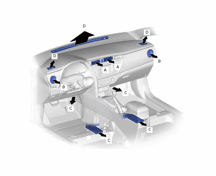
Indication
Mode
FACE
FOOT
DEF
CTR
SIDE
C
D
A
B
FACE


B/L

FOOT

F/D
DEF
The size of each circle ○ indicates the ratio of airflow volume.
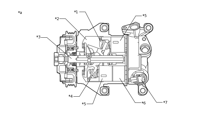
COMPRESSOR
General
The compressor assembly with pulley is a continuously variable capacity type with a capacity that varies in accordance with the cooling load of the air conditioning.
The compressor assembly with pulley consists of the shaft, lug plate, piston, shoe, crank chamber, cylinder and solenoid control valve.
*a
Example
-
-
*1
Shoe
*2
Crank Chamber
*3
Shaft
*4
Lug Plate
*5
Piston
*6
Cylinder
*7
Solenoid Control Valve
-
-
A variable suction side throttle is used.
Refrigerant inlet pressure is applied to the top of the variable suction side throttle and crank chamber pressure is applied to the bottom of the variable suction side throttle.
The pressure difference moves the variable suction side throttle up and down, expanding and contracting the refrigerant inlet passage.
When the refrigerant flow is at a maximum, the refrigerant inlet pressure is greater than the crank chamber pressure. This causes the variable suction side throttle to move down, fully opening the refrigerant inlet passage and lowering the refrigerant inlet pressure.
When the amount of refrigerant flow is controlled, the crank chamber pressure is greater than the refrigerant inlet pressure, raising the variable inlet throttle to contract the flow passage.
These controls suppress noise by reducing pulsation from the refrigerant inlet.
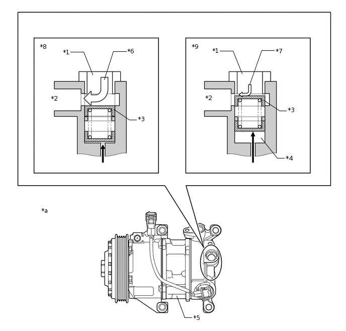
*a
Example
-
-
*1
Refrigerant Passage A
*2
Inlet Chamber
*3
Variable Suction Side Throttle
*4
Crank Pressure Inlet Chamber
*5
Compressor Assembly with Pulley
*6
High Flow
*7
Low Flow
*8
Maximum Volume of Refrigerant
*9
Controlled Volume of Refrigerant
-
-

Crank Chamber Pressure

Refrigerant Flow
A Damper Limiter (DL) type air conditioning pulley is used. A cylinder-type damper is used for this compressor assembly with pulley and torque fluctuations have been suppressed, thus making an inertia weight unnecessary. As a result, the weight of the compressor assembly with pulley has been reduced.
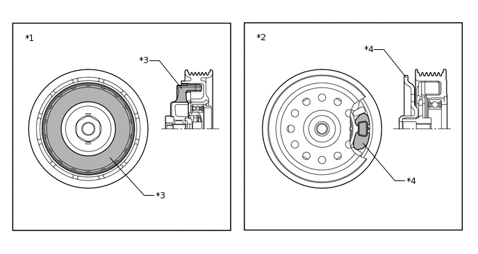
*1
Damper Limiter (DL) Type Air Conditioning Pulley
*2
Conventional Type Air Conditioning Pulley
*3
Damper
*4
Inertia Weight
Operation
The crank chamber is connected to the suction passage. A solenoid control valve is provided between the suction passage (low pressure) and the discharge passage (high pressure).
The solenoid control valve operates under duty cycle control in accordance with the signals from the air conditioning amplifier assembly.
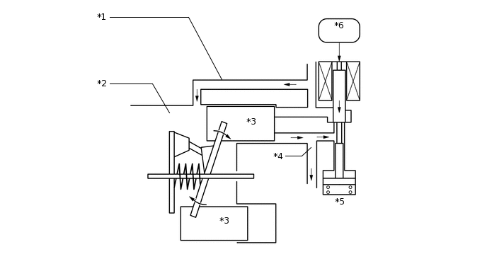
*1
Suction Passage
*2
Crank Chamber
*3
Piston
*4
Discharge Passage
*5
Solenoid Control Valve
*6
Air Conditioning Amplifier Assembly
When the solenoid control valve closes (the solenoid coil is energized), a difference in pressure is created and the pressure in the crank chamber decreases. Then, the pressure applied to the right side of the piston becomes greater than the pressure applied to the left side of the piston. This compresses the spring and tilts the lug plate. As a result, the piston stroke increases and the discharge capacity increases.
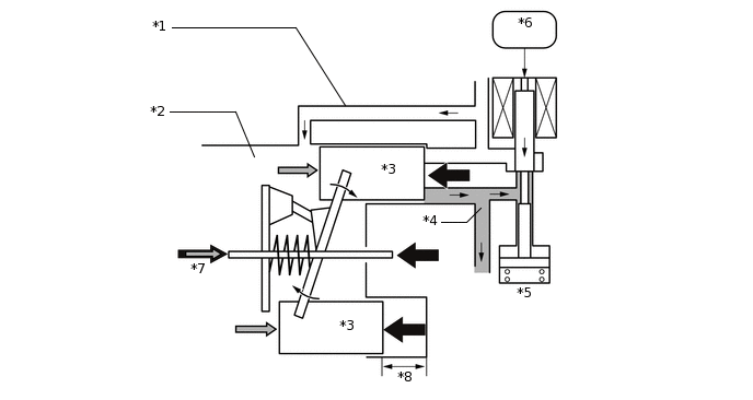
*1
Suction Passage
*2
Crank Chamber
*3
Piston
*4
Discharge Passage
*5
Solenoid Control Valve
*6
Air Conditioning Amplifier Assembly
*7
Crank Chamber Pressure + Spring Force
*8
Piston Stroke: Large
When the solenoid control valve opens (the solenoid coil is not energized), the difference in pressure disappears. Then, the pressure applied to the left side of the piston becomes the same as the pressure applied to the right side of the piston. Thus, the spring elongates and eliminates the tilt of the lug plate. As a result, there is a small piston stroke and the discharge capacity decreases.
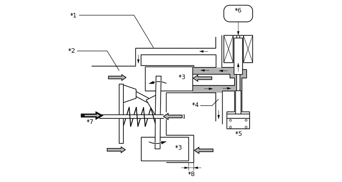
*1
Suction Passage
*2
Crank Chamber
*3
Piston
*4
Discharge Passage
*5
Solenoid Control Valve
*6
Air Conditioning Amplifier Assembly
*7
Crank Chamber Pressure + Spring Force
*8
Piston Stroke: Small
NO. 1 COOLER THERMISTOR
The No. 1 cooler thermistor detects the temperature of the cool air immediately after the evaporator in the form of resistance changes, and outputs it to the air conditioning amplifier assembly.
THERMISTOR ASSEMBLY
The thermistor assembly detects the outside temperature based on changes in the resistance of its built-in thermistor and sends a signal to the combination meter assembly.
AIR CONDITIONER PRESSURE SENSOR
The air conditioner pressure sensor detects the refrigerant pressure and outputs it to the air conditioning amplifier assembly in the form of voltage changes.