ENGINE UNIT
-
CONSTRUCTION
-
Cylinder Head Cover Sub-assembly
-
Lightweight yet high-strength aluminum cylinder head cover sub-assemblies are used.
-
Sealability is ensured with the attachment to the cylinder head through the adoption of constant tightness using an outer flange.
-
An acrylic-rubber cylinder head cover gasket with excellent heat resistance and oil resistance has been adopted.
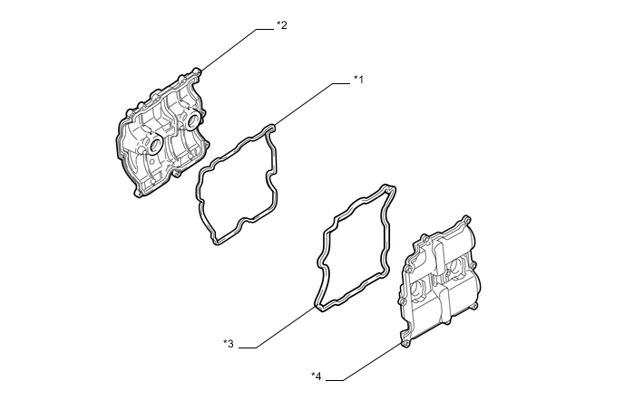
Text in Illustration *1 Cylinder Head Cover Gasket *2 Cylinder Head Cover Sub-assembly RH *3 No.2 Cylinder Head Cover Gasket *4 Cylinder Head Cover Sub-assembly LH
-
-
Cylinder Head Gasket
-
Steel-laminate type cylinder head gaskets are used. A shim is used around the cylinder bore of each gasket to help enhance sealing performance and durability.
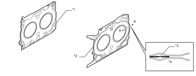
Text in Illustration *1 Cylinder Head Gasket *2 No.2 Cylinder Head Gasket *3 Shim - - *a A - A Cross Section - -
-
-
Cylinder Head Sub-assembly
-
The cylinder head structure is simplified by separating the cam journal portion (camshaft housing sub-assembly) from the cylinder head.
-
A high-pressure fuel pump has been mounted on the cylinder head LH.
-
The cylinder head, which is made of aluminum, contains pentroof-type combustion chambers. The spark plug is located in the center of the combustion chamber in order to improve the engine's anti-knock performance.
-
The crossflow method, which involves mounting the intake port above the engine and the exhaust port below the engine for good efficiency, has been adopted.
-
Pressure loss has been minimized and intake air volume has been increased by optimizing the shape of the intake port.
-
Holes for attaching the direct-injection fuel injector have been added to the inner surface of the cylinder head's intake manifold in conjunction with the adoption of the D-4S system.
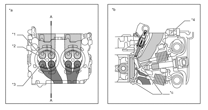
Text in Illustration *1 Intake Valve *2 Spark Plug Hole *3 Exhaust Valve *4 Camshaft Housing Sub-assembly *a Bottom Side View *b A - A Cross Section *c Taper Squish Area - - 
Intake Port 
Exhaust Port Tech Tips
The difference between a siamese type intake port and an independent type one is shown in the illustration.
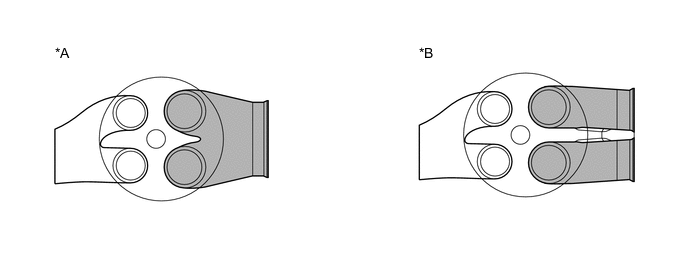
Text in Illustration *A Siamese Type *B Independent Type
-
-
Cylinder Block Sub-assembly
-
The cylinder block sub-assembly is made of aluminum alloy, thus making it lightweight.
-
Overall length has made more compact, with a distance of 113 mm (4.45 in.), between the bore centers of the four horizontally opposed cylinders.
-
Knock control sensors have been place on the left and right sides of the cylinder block sub-assembly, making optimal knock control possible.
-
A compact block has been achieved by producing the thin cast-iron liners and cylinder block sub-assembly as a unit. It is not possible to rebore a block which uses this type of liner.
-
The liners are a undercut-type, which have been manufactured so that their casting exterior forms a large irregular surface in order to enhance the adhesion between the liners and the aluminum cylinder block sub-assembly.
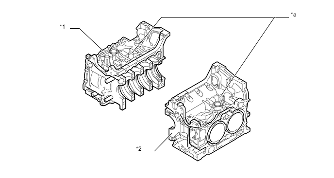
Text in Illustration *1 Cylinder Block Sub-assembly RH *2 Cylinder Block Sub-assembly LH *a Knock Control Sensor Boss - - -
A strengthening rib was added to the rear surface of the cylinder block sub-assembly to improve rigidity.
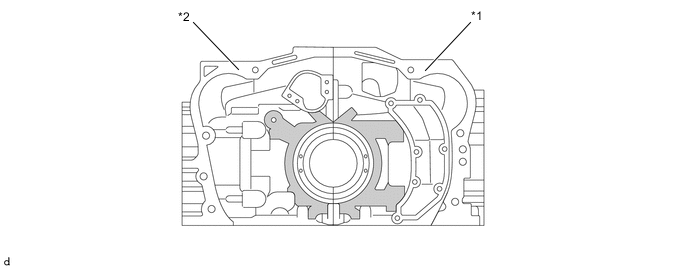
Text in Illustration *1 Cylinder Block Sub-assembly RH *2 Cylinder Block Sub-assembly LH Strengthening Rib - -
-
-
Piston
-
The pistons are made of aluminum alloy.
-
The top of the pistons use a taper squish shape to achieve fuel combustion efficiency.
-
The piston skirt is coated with resin to reduce friction losses.
-
The groove of the top ring is coated with alumite to ensure abrasion resistance.
-
The piston pin length has been shortened to match the tapering of the connecting rod's small end in order to reduce reciprocating inertial load during high engine revolution counts.
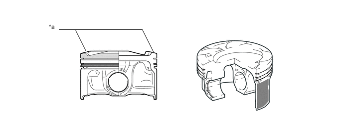
Text in Illustration *a Taper Squish Shape - - Resin Coating Alumite Coating -
FSR-K processing was performed on the piston crown surface and pin boss of the M/T models for the Australia and New Zealand packages to increase strength.
Tech Tips
FSR-K processing: shooting particulates at high-speed generates a reforming layer with a refined morphology on the surface of the raw material. Strengthening the surface layer, which is the starting point of cracks, improves the material fatigue strength.
-
Processed the identification mark to piston crown surface and pin boss of the M/T models for the Australia and New Zealand packages.
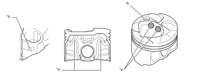
Text in Illustration (Models with M/T for the Australia and New Zealand Packages:) *a FSR-K Processing *b Identification Mark
-
-
Connecting Rod Sub-assembly
-
A taper cut has been adopted for the small end in order to reduce inertial load during high engine revolution counts.
-
A high-strength connecting rod bolt (M9.5) has been adopted in order to inhibit deformation of the large end during high engine revolution counts.
-
The diagonal separation method has been adopted for the large end, with consideration made for ease of maintenance.
-
Copper alloy bearings are used for the connecting rod bearings.
-
The connecting rod bearings are reduced in width to reduce friction.
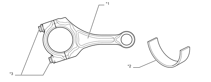
Text in Illustration *1 Connecting Rod Sub-assembly *2 Connecting Rod Bearing *3 Bolt - -
-
-
Crankshaft
-
A crankshaft made of forged steel, which excels in rigidity and wear resistance, is used.
-
The crankshaft has 5 main bearing journals and 8 balance weights.
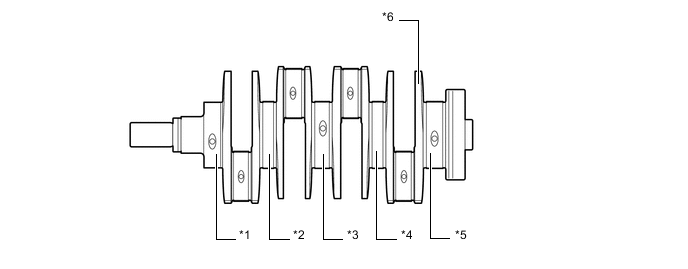
Text in Illustration *1 No. 1 Journal *2 No. 2 Journal *3 No. 3 Journal *4 No. 4 Journal *5 No. 5 Journal *6 Balance Weight
-
-
Crankshaft Bearing
-
The crankshaft main bearings are made of aluminum alloy.
-
Bearings 1, 3 and 5 have been designed with an oil groove.
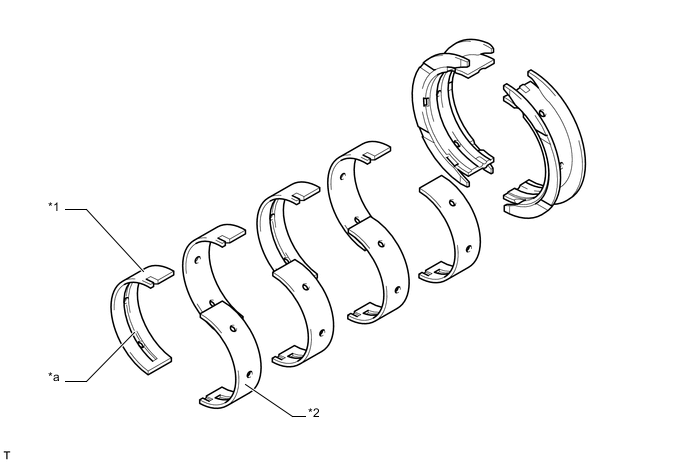
Text in Illustration *1 Crankshaft Bearing RH *2 Crankshaft Bearing LH *a Oil Groove - -
-
-
Oil Pan
-
The oil pan sub-assembly is made of aluminum alloy.
-
The No.2 oil pan sub-assembly is made of steel.
-
The oil pan sub-assembly is secured to the cylinder block sub-assembly and the transmission housing to increase rigidity.
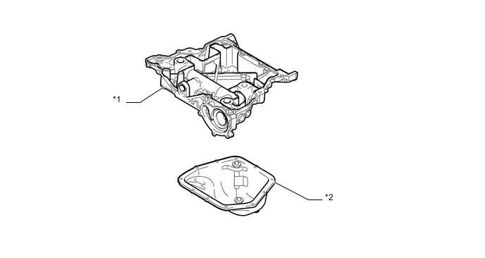
Text in Illustration *1 Oil Pan Sub-assembly *2 No.2 Oil Pan Sub-assembly
-
-
Valve Mechanism
-
Each cylinder of this engine has 2 intake valves and 2 exhaust valves. Intake and exhaust efficiency is increased due to the larger total port areas.
-
A hollow sodium-filled specification has been adopted for the exhaust valve in order to deal with high output, and heat resistance has been improved.
-
This engine uses valve rocker arm sub-assemblies with the built-in needle bearings. This reduces the friction that occurs between the cams and the valve rocker arm sub-assemblies that push the valves down, thus improving fuel economy.
-
The camshafts are driven by the crankshaft via the two chain sub-assemblies.
-
An variable valve timing control system has been adopted. High output and low fuel consumption have been achieved through optimization of intake and exhaust cam shaft timing in accordance with driving conditions.
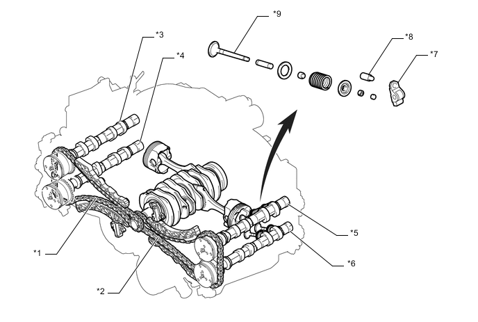
Text in Illustration *1 Chain Sub-assembly RH *2 Chain Sub-assembly LH *3 Intake Camshaft RH *4 Exhaust Camshaft RH *5 Intake Camshaft LH *6 Exhaust Camshaft LH *7 No.1 Valve Rocker Arm Sub-assembly *8 Rocker Arm Pivot *9 Valve - - 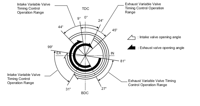
-
-
Camshaft
-
Weight has been reduced by adopting sintered assembly for the cam shaft. A high-lift wide-angle cam profile has been adopted to provide higher output. At the same time, fuel economy at low engine revolution counts and output at high engine revolution counts have both been improved by the adoption of an intermediate lock variable valve timing control. A design has been adopted that operates a vacuum pump (A/T vehicles only) on the camshaft timing intake gear assembly RH and a high-pressure fuel pump on the camshaft timing intake gear assembly LH.
-
Camshaft timing gear assemblies are installed on the front of the intake and exhaust camshafts to vary the timing of the intake and exhaust valves.
-
Together with the use of the No.1 valve rocker arm sub-assemblies, the cam profile has been modified. This results in increased valve lift when the valve begins to open and as it finishes closing, helping to achieve enhanced output performance.
-
The flow rate of the high-pressure fuel pump was optimized, and the lift amount of the cam drive of the intake camshaft LH was reduced to reduce friction.
-
For the sensing-related improvement of the camshaft position sensor, optimized a timing rotor.
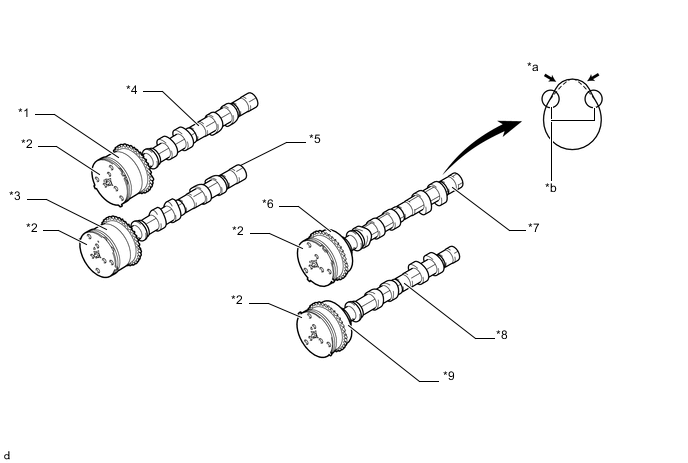
Text in Illustration *1 Camshaft Timing Intake Gear Assembly RH *2 Timing Rotor *3 Camshaft Timing Exhaust Gear Assembly RH *4 Intake Camshaft RH *5 Exhaust Camshaft RH *6 Camshaft Timing Intake Gear Assembly LH *7 Intake Camshaft LH *8 Exhaust Camshaft LH *9 Camshaft Timing Exhaust Gear Assembly LH - - *a Increased Valve Lift *b Modified Profile of Camshaft Lobe
-
-
Variable valve timing control
-
A rotor-based design with high efficiency and low friction while driving has been adopted.
-
Double-tooth rotors have been adopted on both the intake and exhaust sides. When stopped, the rotor on the intake side is fixed in the intermediate locking position, and the rotor on the exhaust side is fixed in the maximum advance position, using lock pins.
-
The variable valve timing control oil control solenoid attached to the timing chain or belt cover sub-assembly activates the spool valve, hydraulic pressure to the advance chamber and retard chamber inside the cam sprocket is regulated, and the phases of the intake and exhaust cam shafts are continuously changed, according to signals from each sensor to the engine control computer.
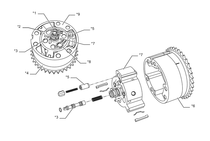
Text in Illustration *1 Retard Check Valve *2 Inlet Check Valve *3 Spool Valve *4 Sprocket *5 Lock Pin *6 Housing and Sprocket *7 Rotor *8 Advance Check Valve *9 Housing - -
-
-
Chain Sub-assemblies and Chain Tensioner Sub-assemblies
-
The chain-driven method has been adopted, making it maintenance-free. The sprocket has been made smaller and the engine more compact by the adoption of an 8-mm-pitch high-strength simplex roller chain for the timing chains.
-
Lighter weight and lower friction have been achieved by adopting a high-strength chain and optimizing the shape of the link plate. This feature is also for a high revolution engine.
-
A hydraulic ratchet tensioner has been adopted. Chain tension has been optimized by the addition of a relief valve on the No.2 chain tensioner assembly.
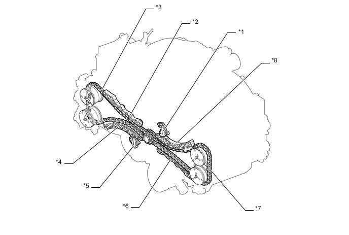
Text in Illustration *1 No.2 Chain Tensioner Assembly *2 No.1 Chain Vibration Damper RH *3 Chain Sub-assembly RH *4 Chain Tensioner Slipper RH *5 No.1 Chain Tensioner Assembly *6 No.1 Chain Vibration Damper LH *7 Chain Sub-assembly LH *8 Chain Tensioner Slipper LH
-
-
Engine Mounting
-
A barycentric suspension support system has been adopted for the engine, with two mounting points at the front and one at the rear.
-
Adaptive hydraulics have been adopted for the front mounts, and the low center of gravity achieves sports car-like handling and a reduction in the transmission of vibrations.
-
The transmission of vibration in the idling range has been suppressed by the adoption of adaptive hydraulic mounts.
-
Weight has been reduced by adopting plastic brackets for the contact points on the engine side.
-
The rear mount is located at the rear end of the transmission. The new installed aluminum crossmember (rear No.2 engine mounting bracket) achieve a significant reduction in weight.
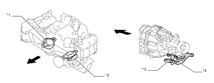
Text in Illustration *1 Front No.1 Engine Mounting Bracket RH *2 Front No.1 Engine Mounting Bracket LH *3 Rear No.1 Engine Mounting Bracket *4 Rear No.2 Engine Mounting Bracket 
Engine Front - -
-
-
V-ribbed Belt
-
A serpentine belt transmission that drives all auxiliary machinery with a single belt has been adopted, shortening the overall engine length, reducing weight, and improving serviceability.
-
An auto-tensioner for V-ribbed belts has been adopted, and in addition to improving the longevity of the belt and auxiliary machinery and making it maintenance free, consideration has been made for serviceability when removing and reattaching the belt. Belt tension is kept within its proper values by a spring installed in the auto-tensioner.
-
Weight has been reduced by the adoption of plastic for No.2 idler pulley sub-assembly.
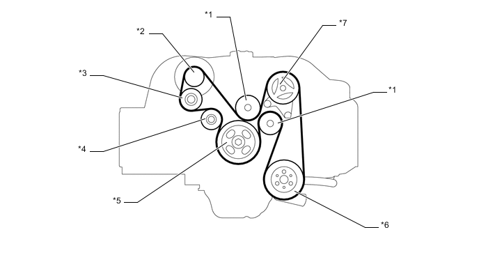
Text in Illustration *1 No.1 Idler Pulley Sub-assembly *2 Generator Pulley *3 No.2 Idler Pulley Sub-assembly (Plastic) *4 Idler Pulley for V-ribbed Belt Tensioner Assembly *5 Crankshaft Pulley *6 Water Pump Pulley *7 Clutch Compressor with Magnet - -
-
-
V-ribbed Belt Tensioner Assembly
-
The tension of the fan and generator V belt is properly maintained by the tension spring that is enclosed in the V-ribbed belt tensioner assembly.
-
-
Vacuum pump
-
A mechanical vacuum pump assembly has been installed as a measure for the reduction of negative pressure within the intake manifold due to significantly delayed ignition timing during rapid warm starts resulting from the change to direct injection.
-
The vacuum pump assembly is attached to the rear end of the intake camshaft on the right-hand camshaft housing and is only installed in automatic transmission vehicles that require pedal pressure (negative pressure) for the amount of creep.
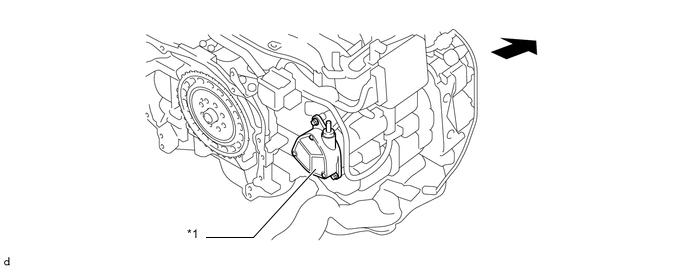
Text in Illustration *1 Vacuum Pump Assembly - - Engine Front - -
-
-